Overhaul
Part 1 Of 2:
Part 2 Of 2:
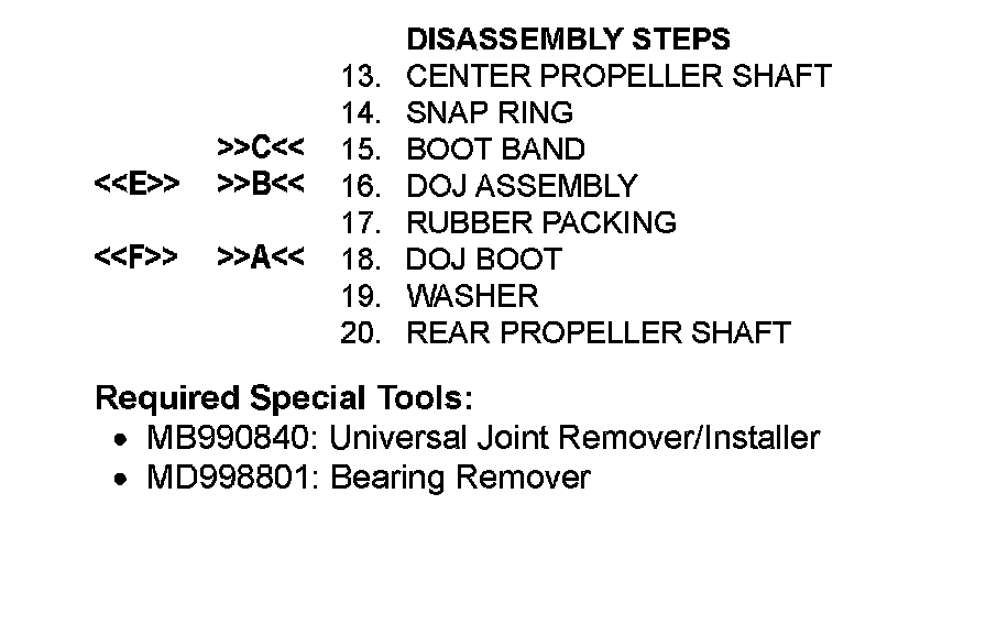
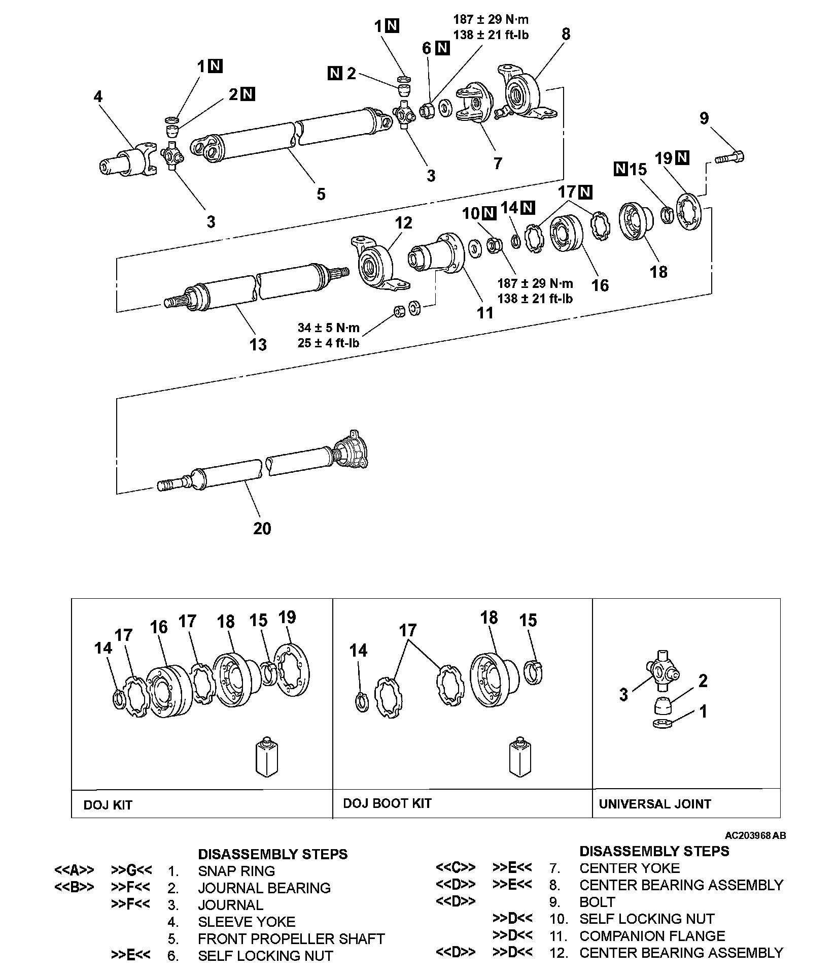
PROPELLER SHAFT
DISASSEMBLY AND ASSEMBLY
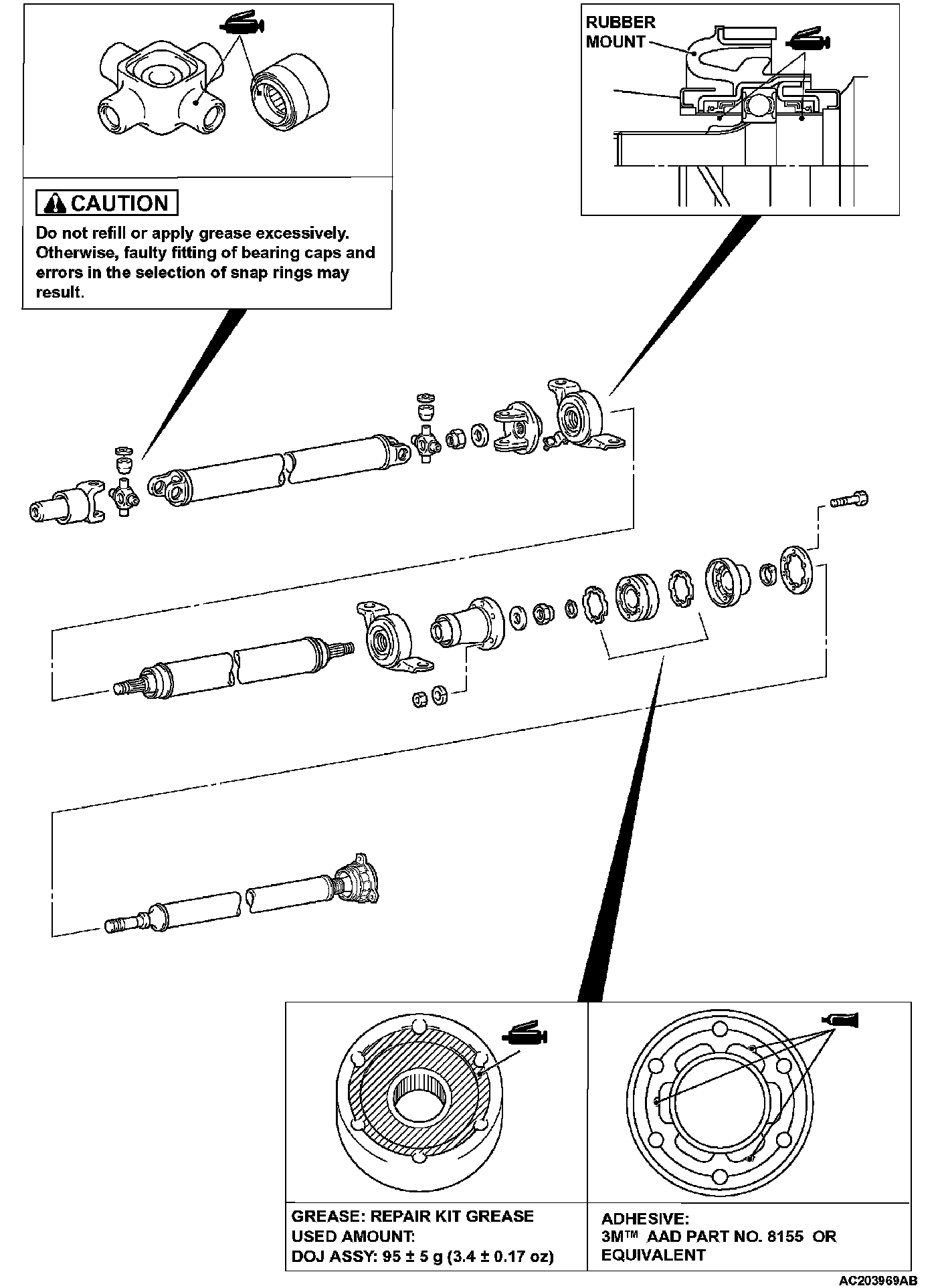
LUBRICATION AND ADHESIVE POINTS
DISASSEMBLY SERVICE POINTS
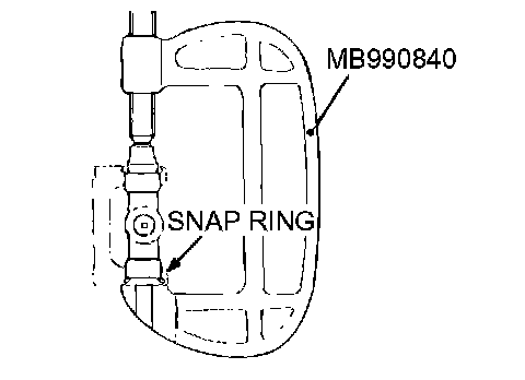
<> SNAP RING REMOVAL
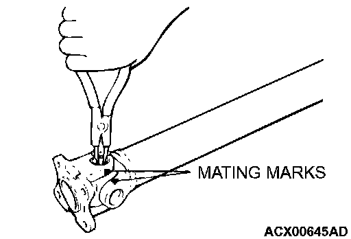
Make mating marks on the flange yoke and propeller shaft. Then, remove the snap rings.
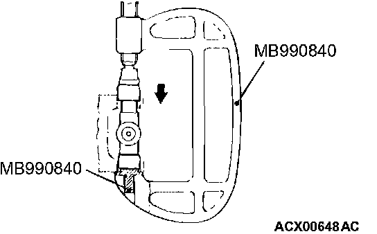
<> JOURNAL BEARING REMOVAL
CAUTION: Do not tap the journal bearings to remove them, as this will upset the balance of the propeller shaft.
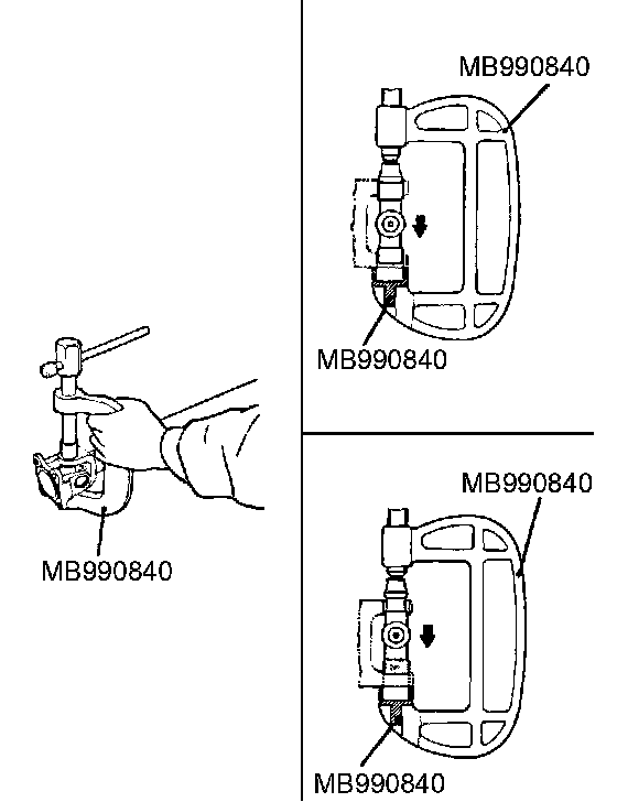
1. Use Special Tool MB990840 to press in the journal bearing on one side, and take out the journal bearing on the opposite side.
2. Insert special tool MB990840 into the other side and press the journal to remove the first journal bearing that was pushed.
<
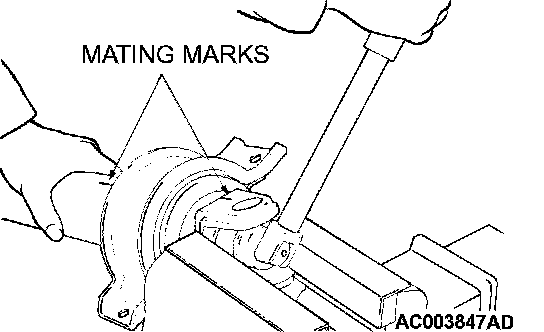
Make mating marks on the center yoke and center propeller shaft, and then remove the center yoke.
<
1. Make mating marks on the rear propeller shaft, DOJ assembly and companion flange, and then remove the bolt.
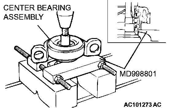
2. Use the special tool MD998801 to remove the center bearing assembly from the center propeller shaft.
<
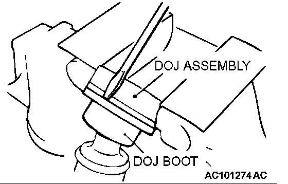
1. Remove the DOJ boot from the DOJ assembly.
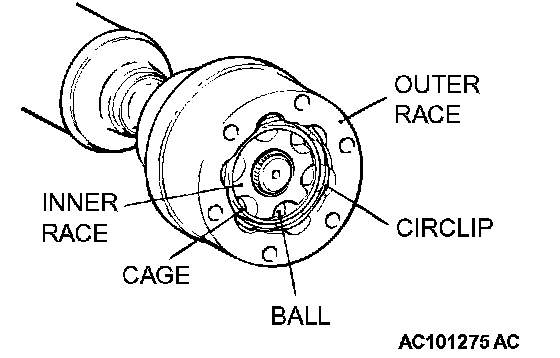
2. Make mating marks on the outer race, cage and inner race, and then remove the circlip, outer race and ball.
NOTE: Note the positions of the balls so that they can be reinstalled in their original positions.
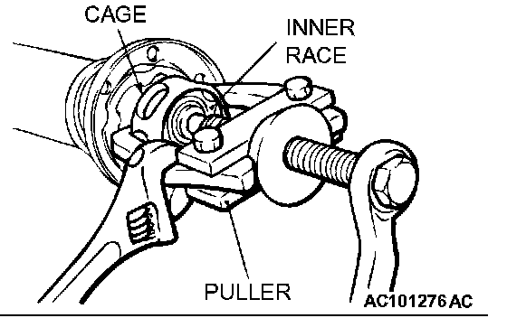
3. Remove the inner race with cage from the center propeller shaft assembly by using a puller (commercially available).
4. Wipe off the grease and clean the outer race, inner race, cage and balls.
<
When the DOJ boot is reused, tape the spline part on the rear propeller shaft and then remove the DOJ boot.
ASSEMBLY SERVICE POINTS
>>A<< DOJ BOOT INSTALLATION
1. Install the boot band.
2. Wrap a plastic tape around the spline part on the rear propeller shaft and then install the DOJ boot.
>>B<< DOJ ASSEMBLY INSTALLATION
1. Apply a thin coat of the specified grease to the ball grooves of the inner and outer races.
Specified grease: Repair kit grease
2. Assemble the DOJ assembly as follows:
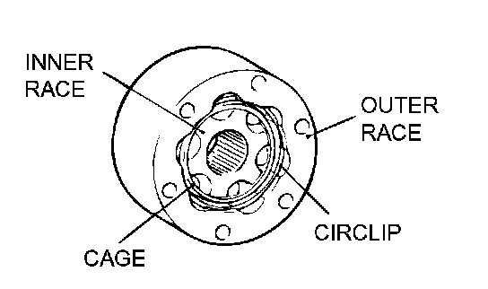
1. Assemble the outer race, cage, balls, and inner race with their mating marks aligned.
2. Install the circlip.
3. Apply specified grease to the DOJ assembly.
Specified grease: Repair kit grease
Amount to use: 95 ± 5 g (3.4 ± 0.17 ounces)
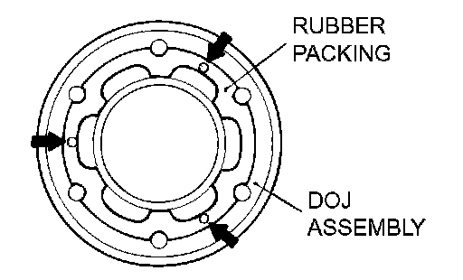
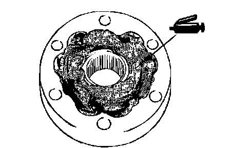
4. Apply a thin coat of specified adhesive to the groove side of DOJ assembly (shown by arrows in the figure) and install the rubber packing. Specified adhesive: 3M(TM) AAD Part No.8155 or equivalent
5. Set the groove side of DOJ assembly (for packing) toward the DOJ boot side and install them.
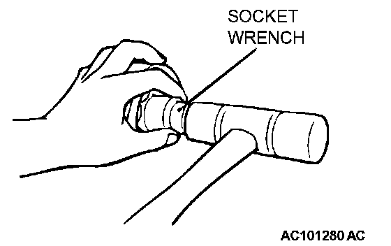
6. Lining up the mating marks on the DOJ assembly and the center propeller shaft and using the socket wrench, install the DOJ assembly to the center propeller shaft.
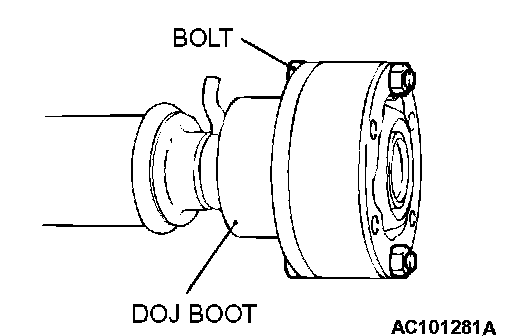
7. Using the bolt, align the bolt holes of the DOJ boot and the DOJ assembly and install DOJ boot to the DOJ assembly.
8. Install the rubber packing of the companion flange side in the same manner as described in (4) above.
>>C<< BOOT BAND INSTALLATION
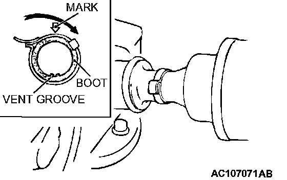
CAUTION:
^ Clamp the boot by holding down the lever at a position nearly opposite to the vent groove provided in the DOJ boot (at arrow marked position on boot).
^ Be sure to remove grease, if present, from around the vent groove. Grease obstructs the ventilation air passage.
>>D<< CENTER BEARING ASSEMBLY/COMPANION FLANGE/SELF-LOCKING NUT INSTALLATION
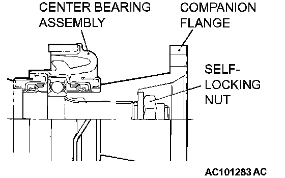
1. Set the center bearing assembly in the direction shown in the figure and install it to the rear propeller shaft.
2. Install, lining up the mating marks on the companion flange and the rear propeller shaft.
3. While tightening the self-locking nut, install the center bearing assembly with the companion flange.
>>E<
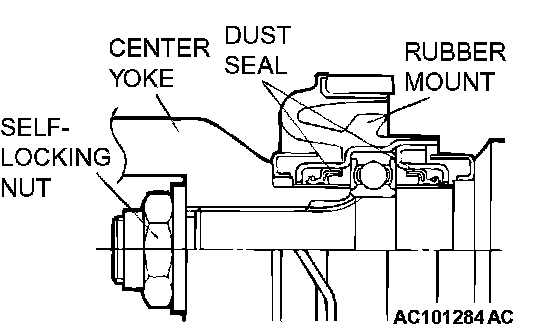
1. Set the center bearing assembly in the direction shown in the figure and install it to the center propeller shaft.
2. Install, lining up the mating marks on the center yoke and the center propeller shaft.
3. While tightening the self-locking nut, install the center bearing assembly with the center yoke.
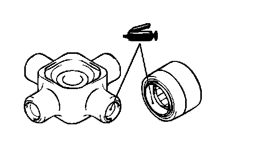
>>F<< JOURNAL/JOURNAL BEARING INSTALLATION
CAUTION: Do not apply grease excessively. Too much grease can result in errors in the selection of snap rings.
1. Apply multi-purpose grease to the following universal joint kit.
^ Shaft and journal grease cup
^ Dust seal lip
^ Needle roller bearing
CAUTION: Be careful when pressing the journal bearings. If they are pressed at an angle, the inside of the journal bearings will be damaged.
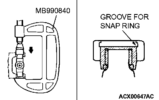
2. Use Special Tool MB990840 to press the journal bearing into the center yoke until the snap ring groove is fully visible.
3. Use Special Tool MB990840 to press the opposite side journal bearing into the yoke.
4. Align the mating marks on the center yoke and rear propeller shaft, and install the propeller shaft journal bearings in the same manner as described in (1) and (2) above.
>>G<< SNAP RING INSTALLATION
1. Install a snap ring to one side of the journal.
2. Use Special Tool MB990840 at the opposite side of the installed snap ring to press in the journal bearing toward the snap ring.
CAUTION: Always use snap rings of equal thickness on both sides.
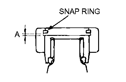
3. Install the snap ring on the opposite side, and measure the clearance of the snap ring groove with a feeler gauge.
Standard value (A): 0.02 - 0.06 mm (0.001 - 0.002 inch) or less
4. If the clearance exceeds the standard value, adjust by changing the thickness of the snap ring