Adjustment of Transaxle
ADJUSTMENT OF TRANSAXLETHRUST WASHER SELECTION FOR ADJUSTMENT OF INPUT SHAFT END PLAY
CAUTION:
^ If solder is not available, select the thrust washer in accordance with Plastigage method.
^ If the thrust washer appropriate for the standard value cannot be selected using solder, select the thrust washer in accordance with Plastigage method.
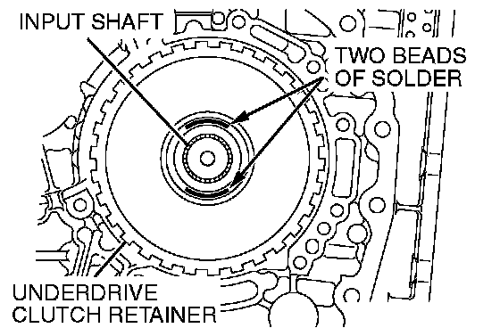
1. Put solders (1.0 mm (0.039 inch) diameter, about 10 mm (0.39 inch) long) in the illustrated positions of the underdrive clutch retainer.
2. Install the adjusting thrust washer having minimum thickness.
CAUTION: Never use a gasket that has been tightened.
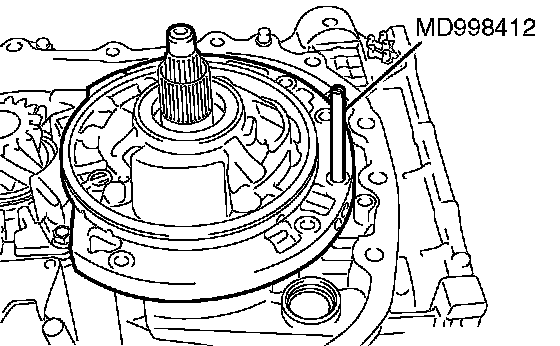
3. Use the special tool Guide (MD998412) to install a new oil pump gasket and the oil pump. Tighten the oil pump mounting bolts to the specified torque of 29 ± 2 Nm (21 ± 2 ft. lbs.).
4. Remove the oil pump mounting bolts.
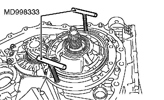
5. Using special tools MD998333, remove the oil pump and then take out crushed solders.
6. If the solders have not crushed, use thicker thrust washer and repeat steps 3 to 5.
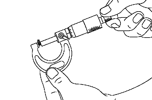
7. Use a micrometer to measure the thickness of the crushed solder beads and record the measured value. Based on the total thickness of the thickness of the measured solder and that of the thrust washer, select the thrust washer so that the end play can have the standard value.
Thrust washer thickness: (T1 + T2 - 0.70 mm (0.028 inch)) to (T1 + T2 - 1.45 mm (0.057 inch))
T1: The crushed solder thickness mm (inch)
T2: The thrust washer thickness used for measurement mm (inch)
Standard value: 0.70 - 1.45 mm (0.028 - 0.057 inch)
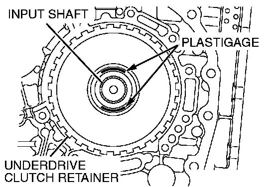
1. Put plastigage (about 10 mm (0.039 inch) long) in the illustrated positions of the underdrive clutch retainer.
2. Install the adjusting thrust washer having the minimum thickness.
CAUTION: Never use a gasket that has been tightened.
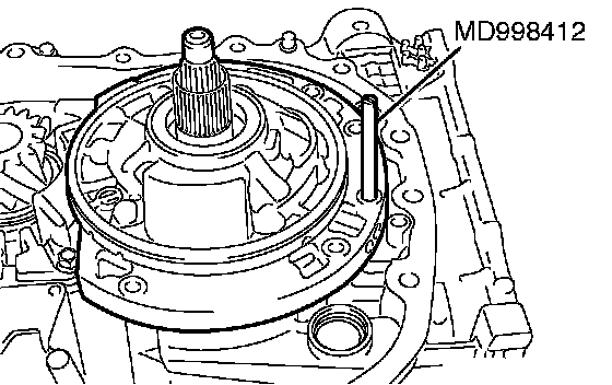
3. Use the special tool Guide (MD998412) to install a new oil pump gasket and the oil pump. Tighten the oil pump mounting bolts to the specified torque of 29 ± 2 Nm (21 ± 2 ft. lbs.).
4. Remove the oil pump mounting bolts.
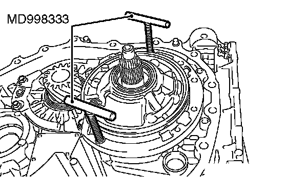
5. Using special tools MD998333, remove the oil pump and then take out crushed Plastigages.
6. If the plastigages have not crushed, use thicker adjusting thrust washer and repeat steps 3 to 5.

7. Measure the width of the crushed plastigage at its widest part using a scale printed on the plastigage package. Based on the total thickness of the thickness of the measured plastigage and that of the thrust washer, select the thrust washer so that the end play can have the standard value.
Thrust washer thickness: (T3 + T2 - 0.70 mm (0.028 inch)) to (T3 + T2 - 1.45 mm (0.057 inch))
T3: The crushed plastigage thickness mm (inch)
T2: The thrust washer thickness used for measurement mm (inch)
Standard value: 0.70 - 1.45 mm (0.028 - 0.057 inch)
SPACER SELECTION FOR ADJUSTMENT OF DIFFERENTIAL CASE PRELOAD
CAUTION:
^ If solder is not available, select the spacer in accordance with Plastigage method.
^ If the spacer appropriate for the standard value cannot be selected using solder, select the spacer in accordance with Plastigage method.
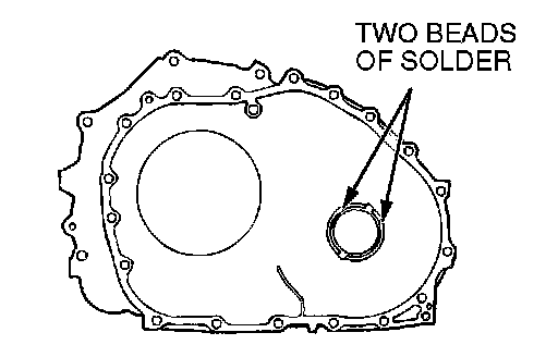
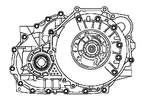
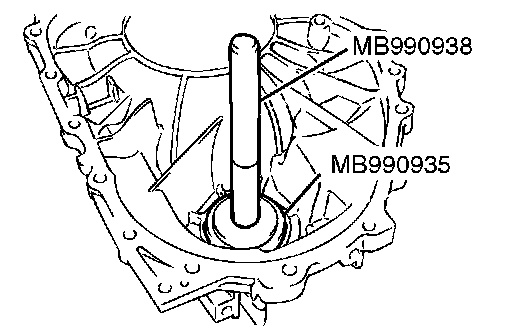
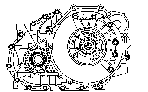
1. Put solders (1.0 mm (0.039 inch) diameter, about 10 mm (0.39 inch) long) in the illustrated positions of the converter housing.
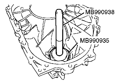
2. Use the special tools to drive the outer race into position.
^ Installer adapter (MB990935)
^ Handle (MB990938)
3. Install the converter housing on the transaxle case without applying FIPG. Tighten the mounting bolts to the specified torque of 48 ± 6 Nm (36 ± 4 ft. lbs.).
4. Remove the bolts and converter housing, and take out the solder pieces.
5. If the solders have not crushed, use thicker solders (1.6 mm (0.063 inch) diameter, about 10 mm (0.39 inch) long) and repeat steps 2 to 4.
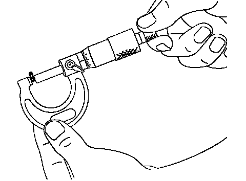
6. Measure the thickness of the crushed solder with a micrometer, and then select a spacer that will provide the standard value.
Spacer thickness: (T1 - 0.045 mm (0.0018 inch)) to (T1 - 0.105 mm (0.0041 inch))
T1: The crushed solder thickness mm (inch)
Standard value: 0.045 - 0.105 mm (0.0018 - 0.0041 inch)
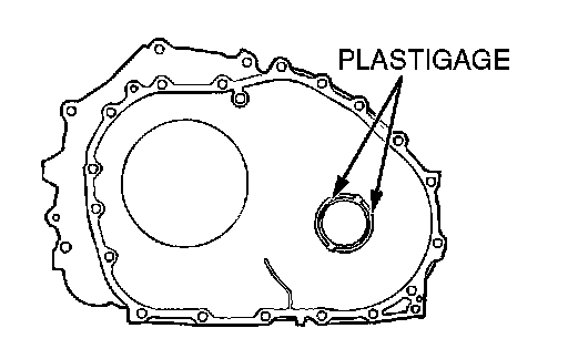
1. Put plastigage (about 10 mm (0.39 inch) long) in the illustrated positions of the converter housing.
2. Install the adjusting spacer having the minimum thickness.
3. Use the special tools to drive the outer race into position.
^ Installer adapter (MB990935)
^ Handle (MB990938)
4. Install the converter housing on the transaxle case without applying FIPG. Tighten the mounting bolts to the specified torque of 48 ± 6 Nm (36 ± 4 ft. lbs.).
5. Remove the bolts and converter housing, and take out crushed plastigage.
6. If the plastigages have not crushed, replace the spacer with a thicker one and repeat steps 3 to 5.
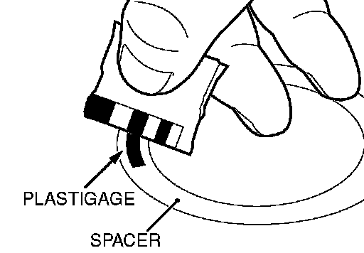
7. Measure the width of the crushed plastigage at its widest part using a scale printed on the plastigage package, and then select a spacer that will provide the standard value.
Spacer thickness: (T3 - 0.045 mm (0.0018 inch)) to (T3 - 0.105 mm (0.0041 inch))
T3: The crushed plastigage thickness mm (inch)
Standard value: 0.045 - 0.105 mm (0.0018 - 0.0041 inch)