Disassembly and Assembly
DISASSEMBLY AND ASSEMBLY
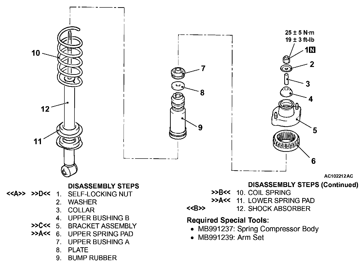
DISASSEMBLY SERVICE POINTS
[[A]] SELF-LOCKING NUT REMOVAL
CAUTION:
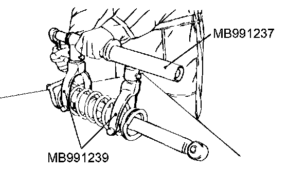
^ To hold the coil spring securely, install the special tools MB991237 and MB991239 evenly, and so that the space between both arms of the special tool will be maximum within the installation range.
^ Do not use an impact wrench to tighten the bolt of the special tool MB991237. It will break the special tool.
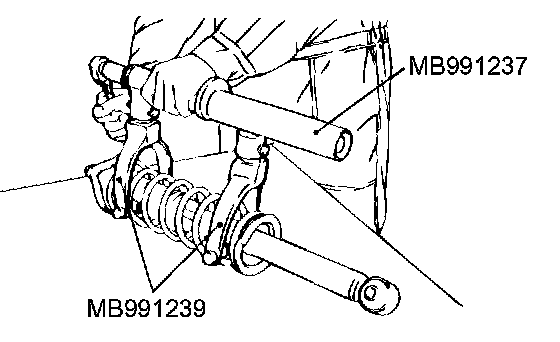
1. Use the special tools MB991237 and MB991239 to compress the coil spring.
WARNING: Do not use an impact wrench to remove the self-locking nut Vibration of the impact wrench will cause the special tools MB991237 and MB991239 to slip and cause personal injury.
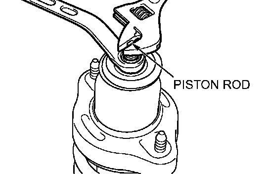
2. While holding the piston rod, remove the self-locking nut.
[[B]] SHOCK ABSORBER REMOVAL
WARNING: Wear goggles when drilling to protect your eyes from flying meter debris.
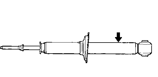
The gas must be discharged from the shock absorber before discarding it. Place the shock absorber horizontally with its piston rod extended. Then drill a hole of approximately 3 mm (0.1 inch) in diameter at the location shown in the illustration and discharge the gas.
ASSEMBLY SERVICE POINTS
]]A[[ LOWER SPRING PAD/UPPER SPRING PAD INSTALLATION BLOWER SPRING PADS
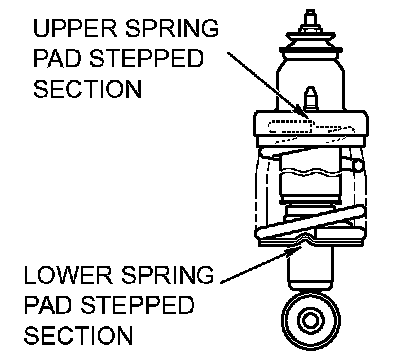
Align the stepped section of the lower spring pad with the stepped section of the spring seat of the shock absorber, and install the lower spring pad.
[UPPER SPRING PAD]
Align the stepped section of the upper spring pad with the end of the coil spring, and install the upper spring pad.
]]B[[ COIL SPRING INSTALLATION
CAUTION: Do not use an impact wrench to tighten the bolt of the special tool MB991237. It will break the special tool.
1. Use the special tools MB991237 and MB991239 to compress the coil spring, and install it to the lower spring pad.
2. Align the end of the coil spring with the stepped section of the lower spring pad.
]]C[[ BRACKET ASSEMBLY INSTALLATION
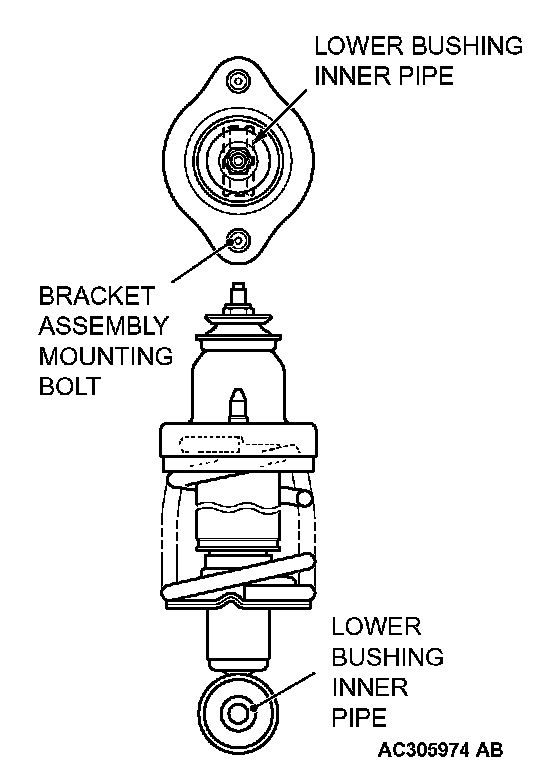
Install the bracket assembly so that the lower bushing inner pipe of the shock absorber and the line between the bracket mounting bolts are straight when looking from above.
]]D[[ SELF-LOCKING NUT INSTALLATION
1. Temporarily tighten the self-locking nut.
CAUTION: Do not use an impact wrench to tighten the self-locking nut, otherwise the self-locking nut will be damaged.
2. Remove the special tools MB991237 and MB991239, and then tighten the self-locking nut to 25 ± 5 Nm (19 ± 3 ft. lbs.).