Front Suspension
Part 1 Of 2:
Part 2 Of 2:
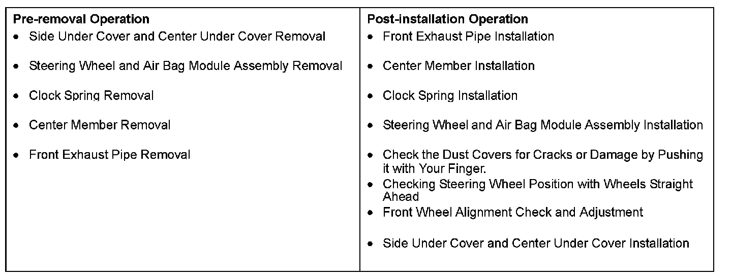
REMOVAL AND INSTALLATION
CAUTION:
^ Before removing the steering wheel and air bag module assembly, refer to Service Precautions and Air Bag Module and Clock Spring. Also, put the front wheels in straight-ahead position. Failure to do so may damage the SRS clock spring and render the SRS air bag inoperative, which results serious driver injury.
^ Indicates parts which should be temporarily tightened, and then fully tightened with the vehicle on the ground in an unladen condition.
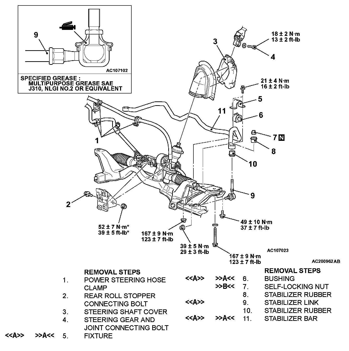
REMOVAL SERVICE POINT
[[A]] FIXTURE/BUSHING/STABILIZER LINK/STABILIZER BAR REMOVAL
Carry out the following operations to ensure working space in order to remove the fixtures, the bushings, the stabilizer links and the stabilizer bar.
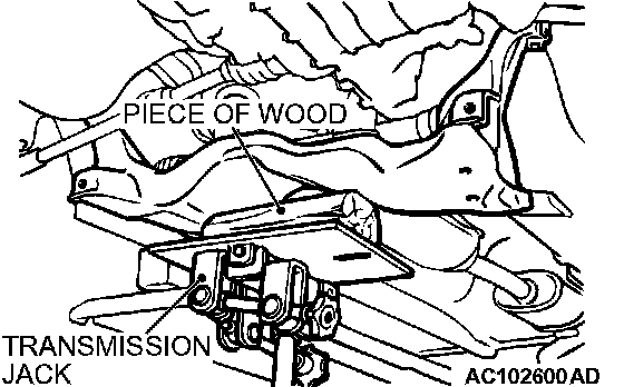
1. Use a transmission jack to hold the crossmember, and then remove the crossmember mounting nuts and bolts.
CAUTION: Be careful not to lower the crossmember excessively, otherwise the power steering return hose bracket may deform.
2. Lower the crossmember until the fixtures, the bushings, the stabilizer links and the stabilizer bar can be removed.
INSTALLATION SERVICE POINTS
]]A[[ STABILIZER BAR/BUSHING/FIXTURE INSTALLATION
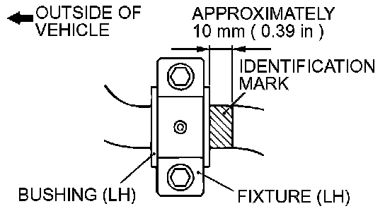
Align the stabilizer bar identification mark with the right end of the bushing (LH).
]]B[[ SELF-LOCKING NUT INSTALLATION
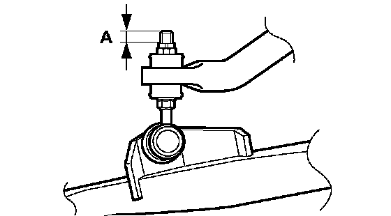
Tighten the self-locking nut until the stabilizer link thread part protruding length meets the standard value.
Standard value (A): 9.4 ± 0.4 mm (0.37 ± 0.02 inch)
INSPECTION
^ Check the bushings for wear and deterioration.
^ Check the stabilizer bar for deterioration or damage.
^ Check all bolts for condition and straightness.
STABILIZER LINK BALL JOINT TURNING TORQUE CHECK
Required Special Tool:
^ MB990326: Preload Socket
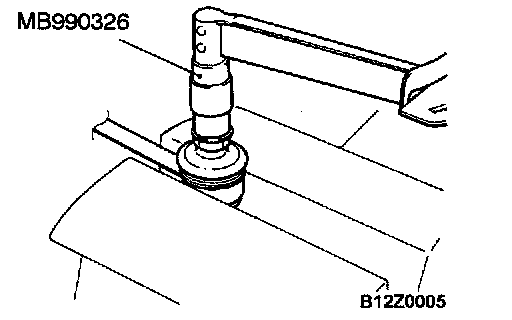
1. After shaking the ball joint stud several times, install the nut to the stud and use the special tool MB990326 to measure the turning torque of the ball joint.
Standard value: 0.5 - 1.5 Nm (4.4 - 13.3 inch lbs.)
2. When the measured value exceeds the standard value, replace the stabilizer link.
3. When the measured value is lower than the standard value, check that the ball joint turns smoothly without excessive play. If so, it is possible to re-use that ball joint.
STABILIZER LINK BALL JOINT DUST COVER CHECK
1. Check the dust cover for cracks or damage by pushing it with your finger.
2. If the dust cover is cracked or damaged, replace the stabilizer link.
NOTE: Cracks or damage of the dust cover may cause damage to the ball joint. When it is damaged during service work, replace the dust cover.
STABILIZER LINK BALL JOINT DUST COVER REPLACEMENT
Only when the dust cover is damaged accidentally during service work, replace the dust cover as follows:
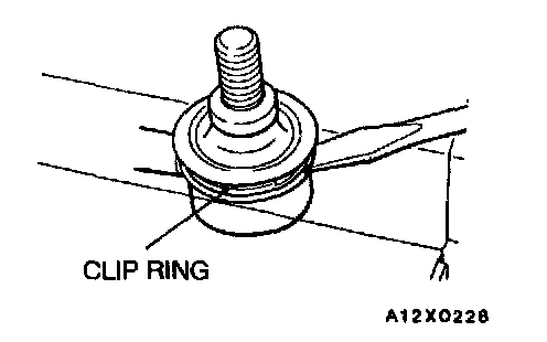
1. Remove the clip ring and the dust cover.
2. Apply the multipurpose grease SAE J310, NLGI No.2 or equivalent to the inside of a new dust cover.
3. Wrap plastic tape around the stabilizer link stud, and then install the dust cover to the stabilizer link.
4. Secure the dust cover by the clip ring.
5. Check the dust cover for cracks or damage by pushing it with finger.