Inspection Procedure 3
INSPECTION PROCEDURE 3: Fuel Gauge does not Work.Fuel Gauge Circuit Part 1:
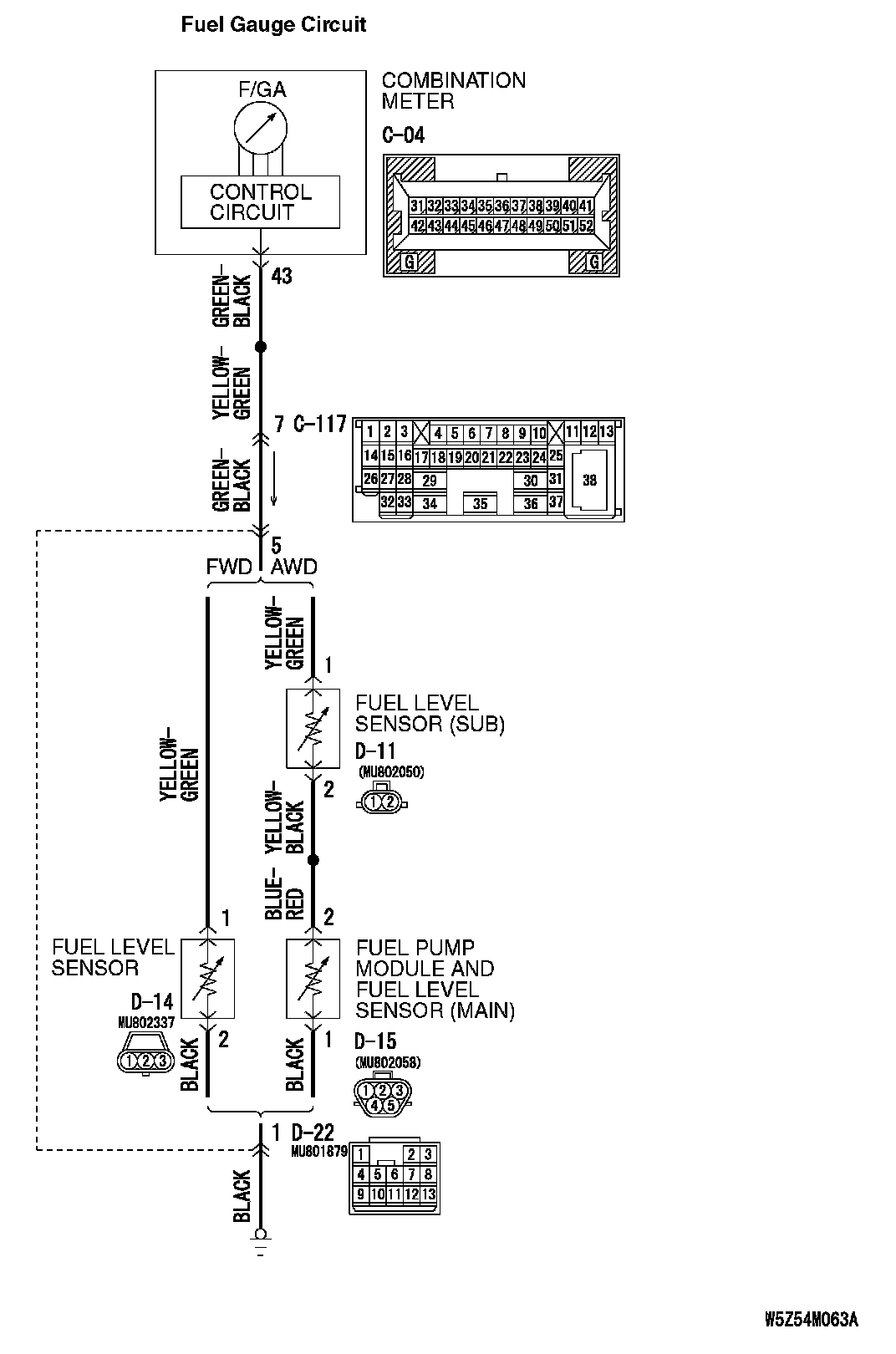
Fuel Gauge Circuit Part 2:
CIRCUIT OPERATION
- The ignition switch (IG1) circuit is the power source for the fuel gauge.
- The resistance value fluctuates causing the circuit current to fluctuate when the fuel level sensor the float moves up and down.
- The fuel gauge moves the needle by the circuit current.
TECHNICAL DESCRIPTION (COMMENT)
The cause is thought to be due to malfunction of the fuel level sensor, fuel pump and gauge unit or combination meter.
TROUBLESHOOTING HINTS
- Malfunction of the fuel pump module and fuel level sensor (main)
- Malfunction of the fuel level sensor
- Malfunction of the combination meter (printed-circuit board or fuel gauge assembly)
DIAGNOSIS
Required Special Tool:
MB991223: Harness Set
STEP 1. Check with other meter.
Check to see that the speedometer, fuel gauge and water thermometer operate normally.
Q: Do all other meters operate?
YES
NO
STEP 2. Check the malfunctioning vehicle.
Q: Is the malfunctioning vehicle a FWD?
YES
NO
STEP 3. Check the fuel level sensor.
Check to see if the fuel level sensor is normal.
Q: Is the fuel level sensor normal?
YES: Go to Step 4.
NO: Replace the fuel level sensor. The fuel gauge should work normally.
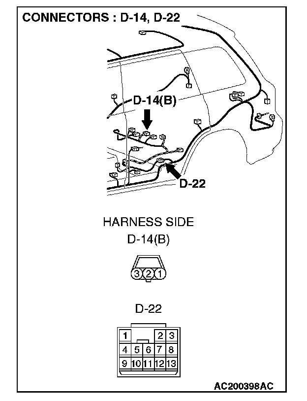
STEP 4. Measure at fuel level sensor connector D-14 in order to the ground circuit to the fuel level sensor.
1. Disconnect fuel level sensor connector D-14, and measure at the wiring harness side.
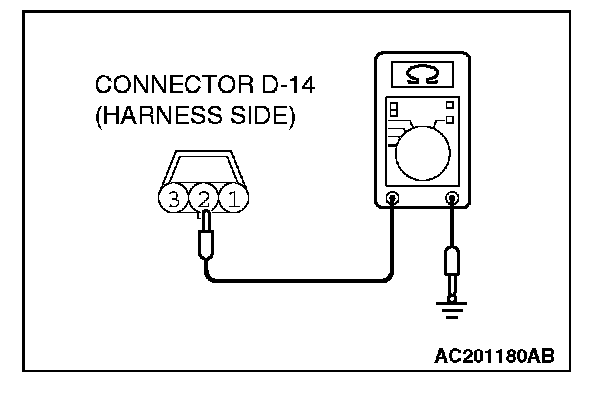
2. Measure the resistance value between terminal 2 and ground.
- The measured value should be 2 ohm or less.
Q: Does the measured resistance value correspond with this range?
YES: Go to Step 7.
NO: Go to Step 5.
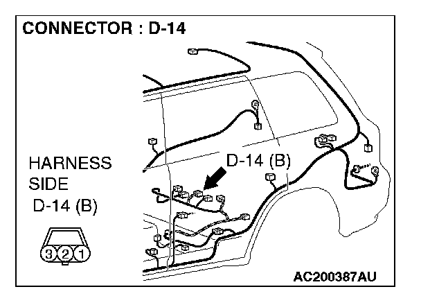
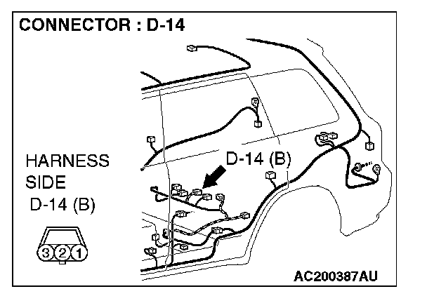
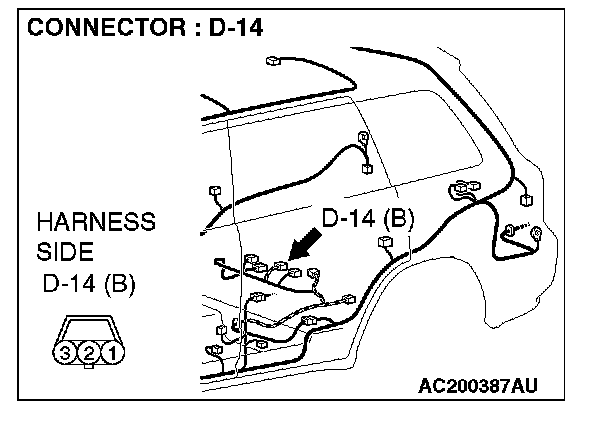
STEP 5. Check fuel level sensor connector D-14 for damage.
Q: Is fuel level sensor connector D-14 in good condition?
YES: Go to Step 6.
NO: Repair or replace the connector. The fuel gauge should work normally.
STEP 6. Check the wiring harness between fuel level sensor connector D-14 (terminal 2) and ground.
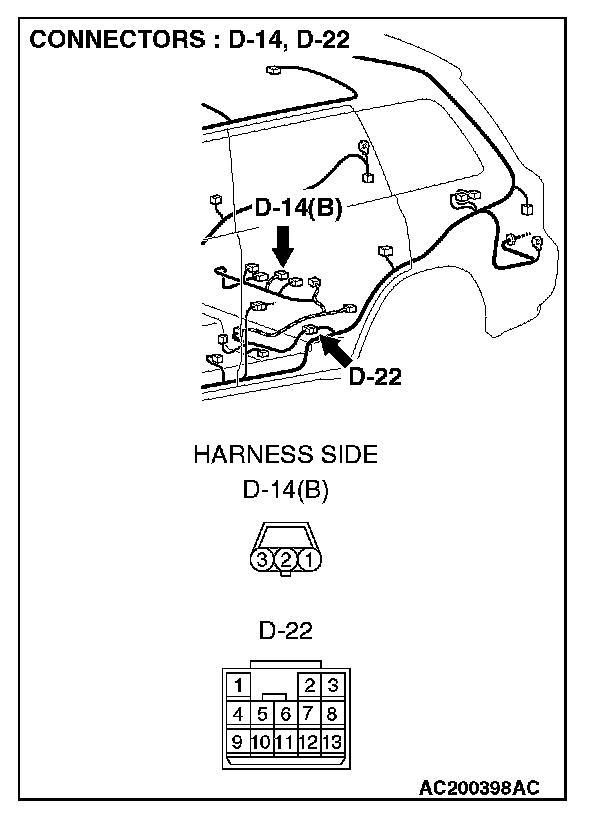
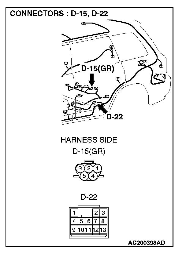
NOTE: Also check intermediate connector D-22. If intermediate connector D-22 is damaged, repair or replace the connector as described in Harness Connector Inspection.
Q: Is the wiring harness between fuel level sensor connector D-14 (terminal 2) and ground in good condition?
YES: There is no action to be taken.
NO: Repair the wiring harness. The fuel gauge should work normally.
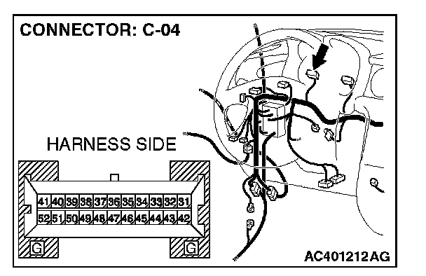
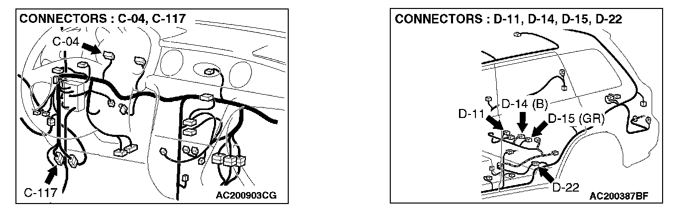
STEP 7. Check fuel level sensor connector D-14 and combination meter connector C-04 for damage.
Q: Are fuel level sensor connector D-14 and combination meter connector C-04 in good condition?
YES: Go to Step 8.
NO: Repair or replace the connector. The fuel gauge should work normally.
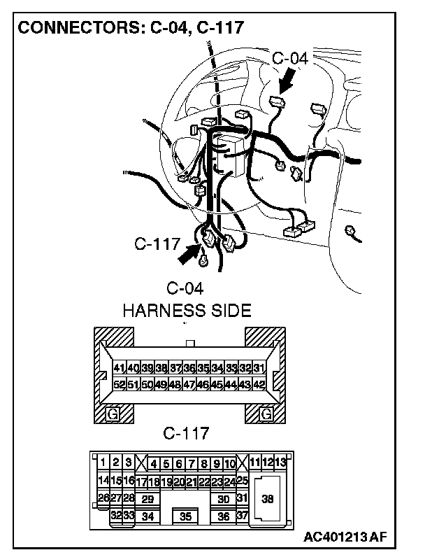
STEP 8. Check the wiring harness between fuel level sensor connector D-14 (terminal 1) and combination meter connector C-04 (terminal 43).
NOTE: Also check intermediate connectors C-117 and D-22. If intermediate connector C-117 or D-22 are damaged, repair or replace the connector as described in Harness Connector Inspection.
Q: Are the wiring harness between fuel level sensor connector D-14 (terminal 1) and combination meter connector C-04 (terminal 43) in good condition?
YES: Repair or replace the combination meter. The fuel gauge should work normally.
NO: Repair the wiring harness. The fuel gauge should work normally.
STEP 9. Check the fuel level sensor (sub) and fuel level sensor (main).
Check to see that the fuel level sensor (sub) and fuel level sensor (main) are normal.
Q: Are fuel level sensor (sub) and fuel level sensor (main) normal?
YES: Go to Step 10.
NO: Replace fuel level sensor (sub) and fuel level sensor (main). The fuel gauge should work normally.
STEP 10. Measure at fuel pump module and fuel level sensor connector D-15 in order to the ground circuit to the fuel pump and gauge unit.
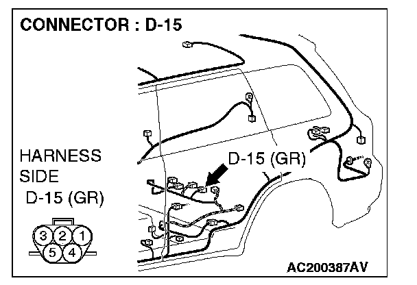
1. Disconnect fuel level sensor connector D-15, and measure at the wiring harness side.
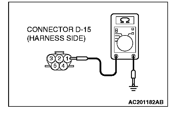
2. Measure the resistance value between terminal 1 and ground.
The measured value should be 2 ohms or less.
Q: Does the measured resistance value correspond with this range?
YES: Go to Step 13.
NO: Go to Step 11.
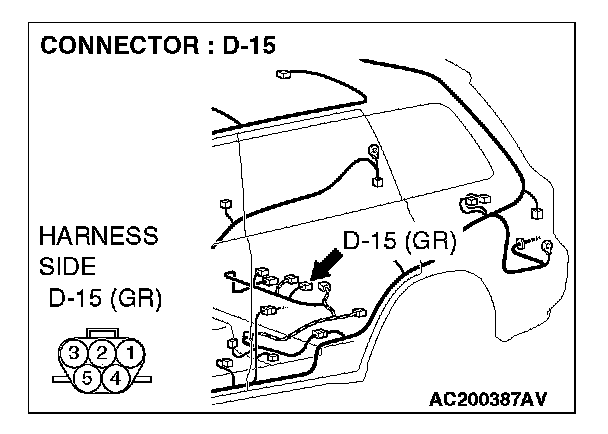
STEP 11. Check fuel pump module and fuel level sensor connector D-15 for damage.
Q: Is fuel pump module and fuel level sensor connector D-15 in good condition?
YES: Go to Step 12.
NO: Repair or replace the connector. The fuel gauge should work normally.
STEP 12. Check the wiring harness between fuel pump module and fuel level sensor connector D-15 (terminal 1) and ground.
NOTE: Also check intermediate connector D-22. If intermediate connector D-22 is damaged, repair or replace the connector as described in Harness Connector Inspection.
Q: Is the wiring harness between fuel pump module and fuel level sensor connector D-15 (terminal 1) and ground in good condition?
YES: There is no action to be taken.
NO: Repair the wiring harness. The fuel gauge should work normally.
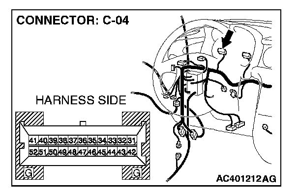
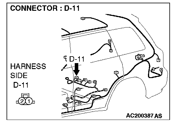
STEP 13. Check fuel level sensor connector D-11 and combination meter connector C-04 for damage.
Q: Are fuel level sensor connector D-11 and combination meter connector C-04 in good condition?
YES: Go to Step 14.
NO: Repair or replace the connector. The fuel gauge should work normally.
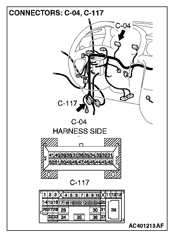
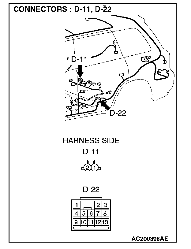
STEP 14. Check the wiring harness between fuel level sensor connector D-11 (terminal 1) and combination meter connector C-04 (terminal 43).
NOTE: Also check intermediate connectors C-117 and D-22. If intermediate connector C-117 or D-22 are damaged, repair or replace the connector as described in Harness Connector Inspection.
Q: Are the wiring harness between fuel level sensor connector D-11 (terminal 1) and combination meter connector C-04 (terminal 43) in good condition?
YES: Go to Step 15.
NO: Repair the wiring harness. The fuel gauge should work normally.
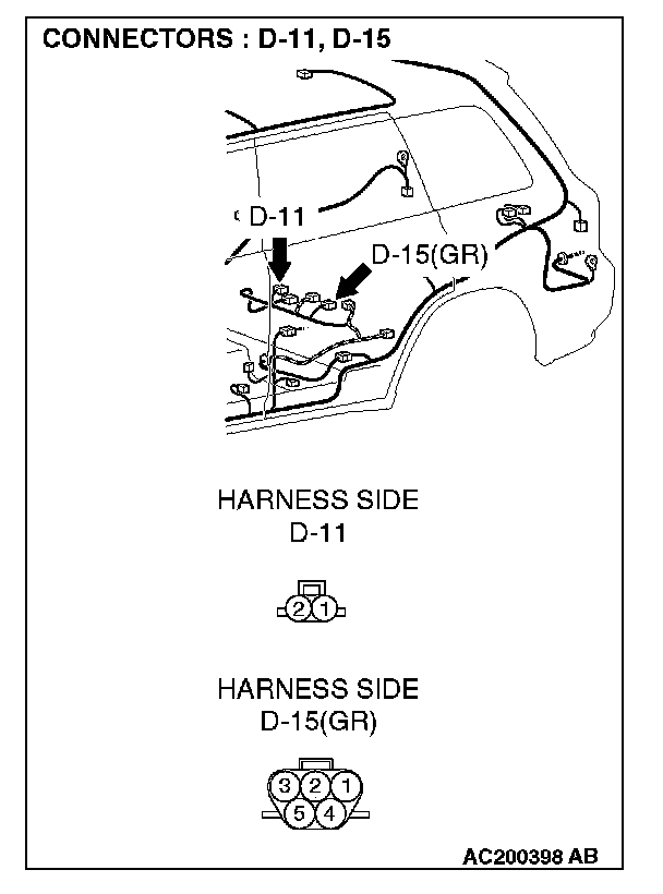
STEP 15. Check fuel level sensor connector D-11 and fuel pump and gauge unit connector D-15 for damage.
Q: Are fuel level sensor connector D-11 and fuel pump and gauge unit connector D-15 in good condition?
YES: Go to Step 16.
NO: Repair or replace the connector. The fuel gauge should work normally.
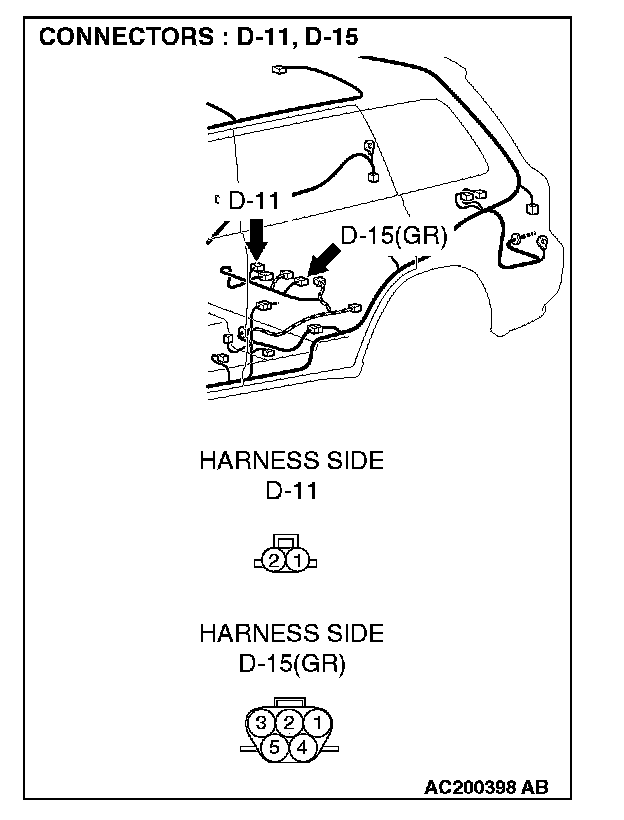
STEP 16. Check the wiring harness between fuel level sensor connector D-11 (terminal 2) and fuel pump module and fuel level sensor connector D-15 (terminal 2).
Q: Are the wiring harness between fuel level sensor connector D-11 (terminal 2) and fuel pump module and fuel level sensor connector D-15 (terminal 2) in good condition?
YES: Repair or replace the combination meter. The fuel gauge should work normally.
NO: Repair the wiring harness. The fuel gauge should work normally.