Inspection Procedure 4
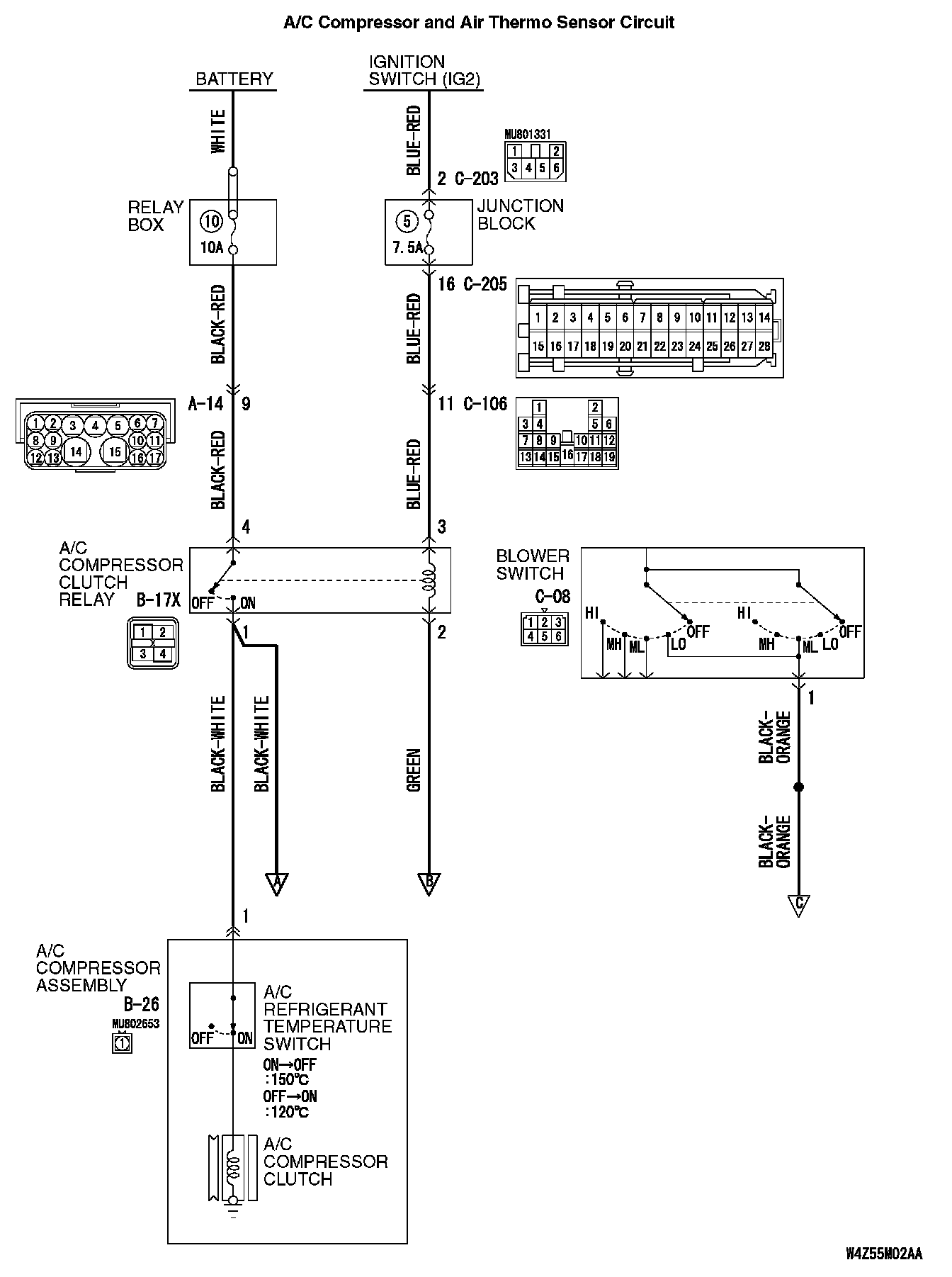
INSPECTION PROCEDURE 4: When the A/C is Operating, Temperature Inside the Passenger Compartment does not Decrease (Cool Air is not Emitted).A/C Compressor And Air Thermo Sensor Circuit Part 1:
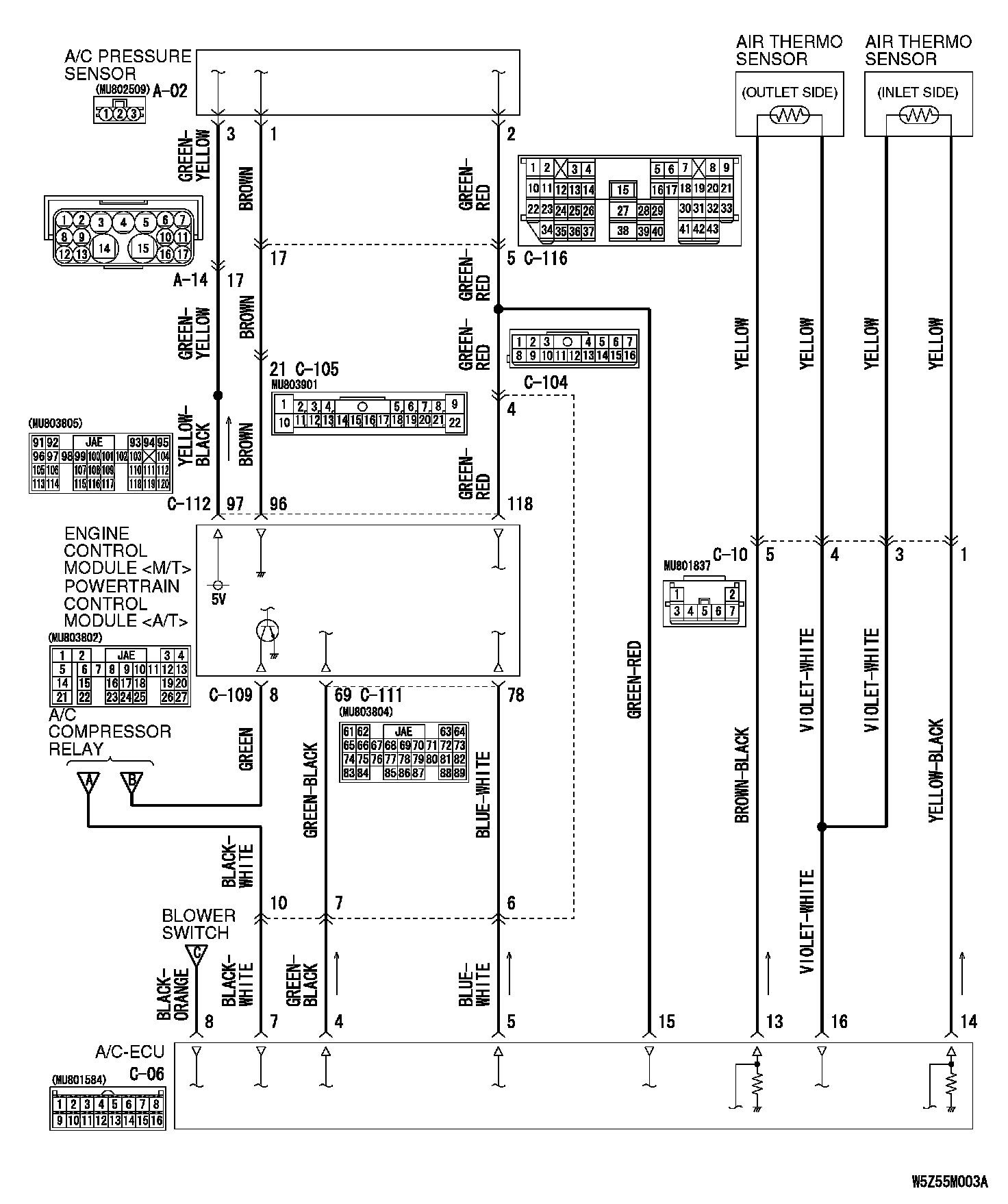
A/C Compressor And Air Thermo Sensor Circuit Part 2:
A/C Compressor And Air Thermo Sensor Circuit Part 3:
CIRCUIT OPERATION
If cool air is not distributed when the A/C switch is on, the air thermo sensor or the A/C compressor clutch relay system may be defective.
TROUBLESHOOTING HINTS
- Improper amount of refrigerant
- Malfunction of the air thermo sensor
- Malfunction of the A/C pressure sensor
- Malfunction of the A/C compressor clutch relay
- Malfunction of the A/C refrigerant temperature switch
- Malfunction of the A/C compressor clutch
- Malfunction of the A/C-ECU
- Malfunction of the PCM
- Damaged harness wires or connectors
DIAGNOSIS
Required Special Tool:
- MB991223: Test Harness Set
STEP 1. Check the rear window defogger and outside/inside air selection damper control motor operation.
Q: Do the rear window defogger and outside/inside air selection damper control motor work normally?
YES: Go to Step 2.
NO: Refer to Inspection procedure 11 "Malfunction of the A/C-ECU Power supply system."
STEP 2. Check the blower motor operation.
Q: Does the blower motor work normally?
YES: Go to Step 3.
NO: Refer to Inspection procedure 5 "Blower Fan and motor do not turn."
STEP 3. Check the refrigerant level.
Q: Is the refrigerant level correct?
YES: Go to Step 4.
NO: Correct the refrigerant level. Check that the air conditioning works normally.
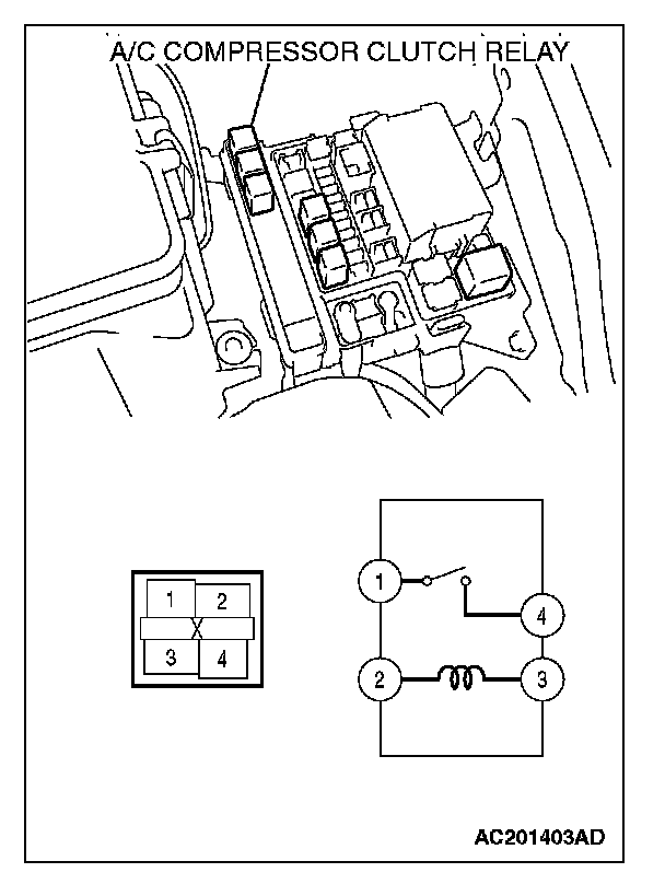
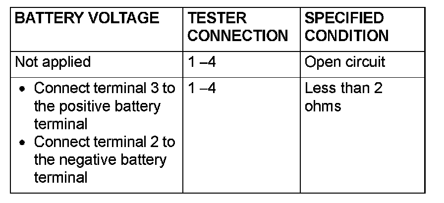
STEP 4. Check the A/C compressor clutch relay continuity.
Follow the table to check the A/C compressor clutch relay for continuity.
Q: Is the A/C compressor clutch relay in good condition?
YES: Go to Step 5.
NO: Replace the A/C compressor clutch relay. Check that the air conditioning works normally.
STEP 5. Check the refrigerant temperature switch.
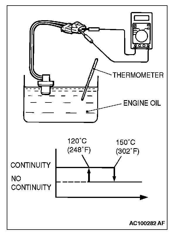
1. Immerse the refrigerant temperature sensor probe into heated engine oil to heat the sensor probe.
CAUTION: Do not heat the sensor probe more than necessary.
2. When the oil temperature reaches the standard value, check that voltage is supplied between the terminals.
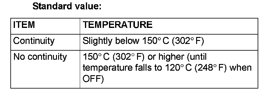
Standard value:
Q: Is the refrigerant temperature switch operating properly?
YES: Go to Step 6.
NO: Replace the refrigerant temperature switch. Check that the air conditioning works normally.
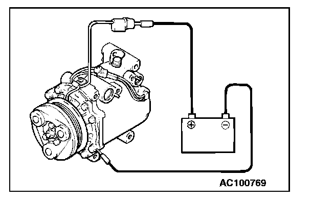
STEP 6. Check the A/C compressor clutch operation.
Connect the positive battery terminal to the compressor A/C compressor clutch connector terminal and ground the battery (-) terminal to the body of the compressor.
Q: Can the sound of the A/C compressor clutch (click) be heard?
YES: Go to Step 7.
NO: Replace the compressor A/C compressor clutch. Check that the air conditioning works normally.

STEP 7. Check the air thermo sensor (outlet side)
1. Measure the resistance between air thermo sensor (outlet side) terminal numbers 4 and 5 at two points or more.
2. Check that the measured value corresponds with approximately the shown value.
Q: Is the air thermo sensor (outlet side) in good condition?
YES: Go to Step 8.
NO: Replace the air thermo sensor. Check that the air conditioning works normally.
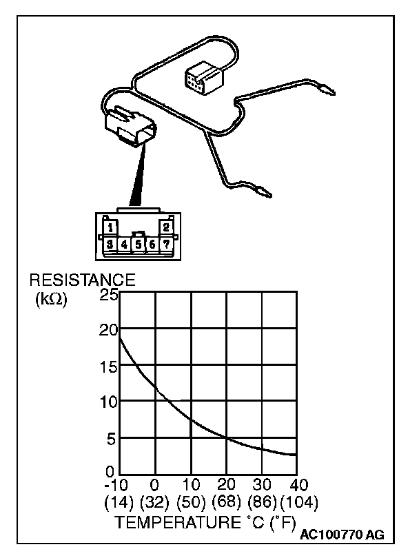
STEP 8. Check the air thermo sensor (inlet side)
1. Measure the resistance between air thermo sensor (inlet side) terminal numbers 1 and 3 at two points or more.
2. Check that the measured value corresponds with approximately the shown value.
Q: Is the air thermo sensor (inlet side) in good condition?
YES: Go to Step 9.
NO: Replace the air thermo sensor. Check that the air conditioning works normally.
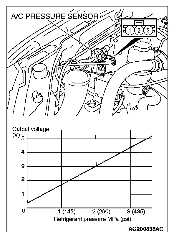
STEP 9. Check the A/C pressure sensor operation.
1. Assemble a manifold gauge onto the high pressure service valve.
2. Turn ON the engine and then turn ON the A/C switch.
3. At this time, check to see that the voltage between the A/C pressure sensor terminal No. 2 and body ground reflects the specifications of the Figure.
NOTE: The allowance shall be defined as 5%.
Q: Is the A/C pressure sensor operating properly?
YES: Go to Step 10.
NO: Replace the A/C pressure sensor. Check that the air conditioning works normally.
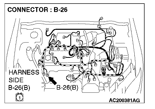
STEP 10. Measure the voltage at A/C compressor connector B-26.

1. Disconnect A/C compressor connector B-26 and measure the voltage at the relay box side.
2. Turn the ignition switch to the "ON" position.
3. Turn the A/C switch to the "ON" position.
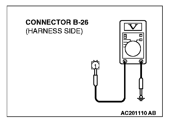
4. Measure the voltage between terminal 1 and ground.
- The measured value should be approximately 12 volts (battery positive voltage).
Q: Does the measured voltage correspond with this range?
YES: Go to Step 21.
NO: Go to Step 11.
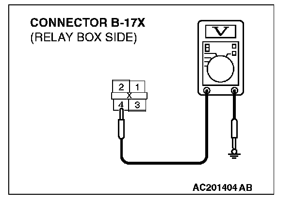
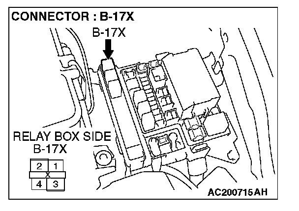
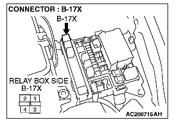
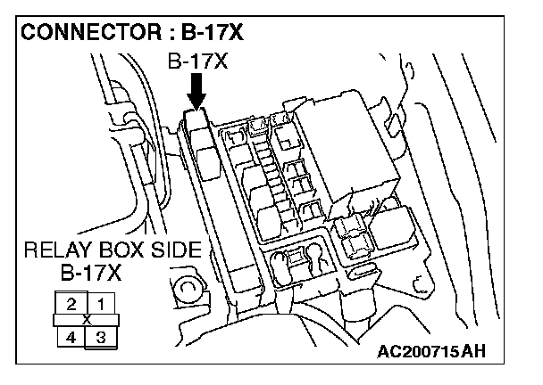
STEP 11. Measure the voltage at A/C compressor clutch relay connector B-17X.
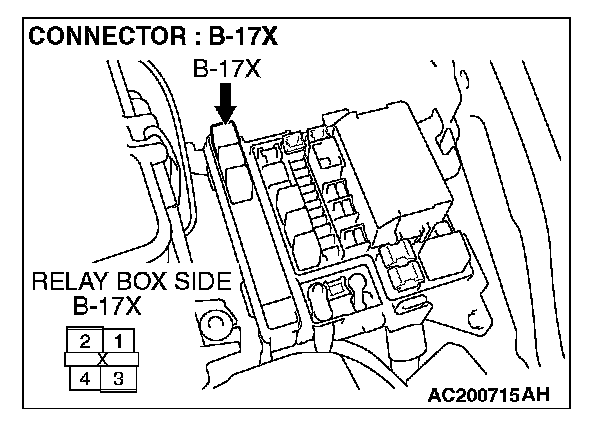
1. Disconnect A/C compressor connector B-17X and measure the voltage at the relay box side.
2. Turn the ignition switch to the "ON" position.
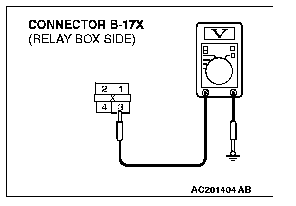
3. Measure the voltage between terminal 3 and ground.
- The measured value should be approximately 12 volts (battery positive voltage).
Q: Does the measured voltage correspond with this range?
YES: Go to Step 14.
NO: Go to Step 12.
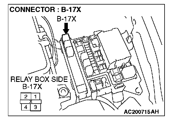
STEP 12. Check A/C compressor clutch relay connector B-17X for damage.
Q: Is A/C compressor clutch relay connector B-17X in good condition?
YES: Go to Step 13.
NO: Repair or replace the connector. Check that the air conditioning works normally.
STEP 13. Check the wiring harness between A/C compressor clutch relay connector B-17X (terminal 3) and the ignition switch (IG2).
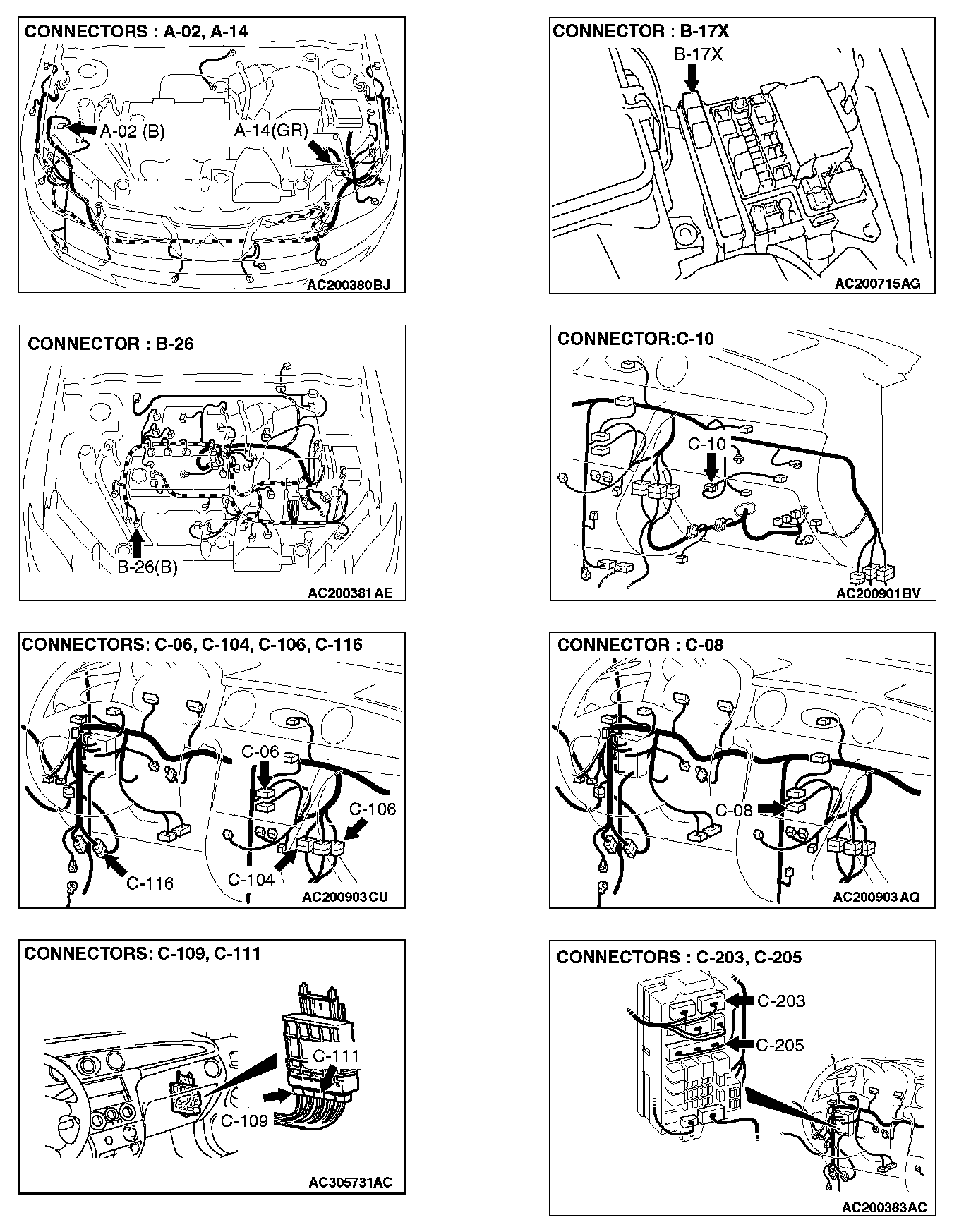
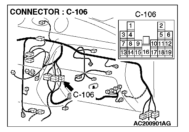
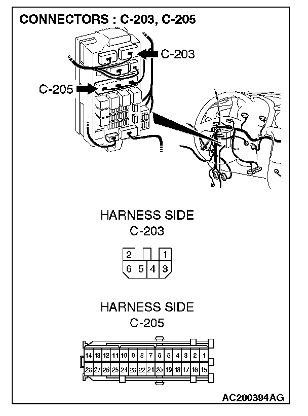
NOTE: Also check intermediate connector C-106, junction block connectors C-205 and C-203. If intermediate connector C-106 or junction block connectors C-205 or C-203 is damaged, repair or replace the connector as described in Harness Connector Inspection.
Q: Is the wiring harness between A/C compressor clutch relay connector B-17X (terminal 3) and the ignition switch (IG2) in good condition?
YES: Check that the air conditioning works normally.
NO: Repair the wiring harness. Check that the air conditioning works normally.
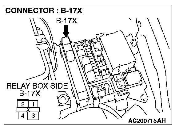
STEP 14. Measure the voltage at A/C compressor clutch relay connector B-17X.
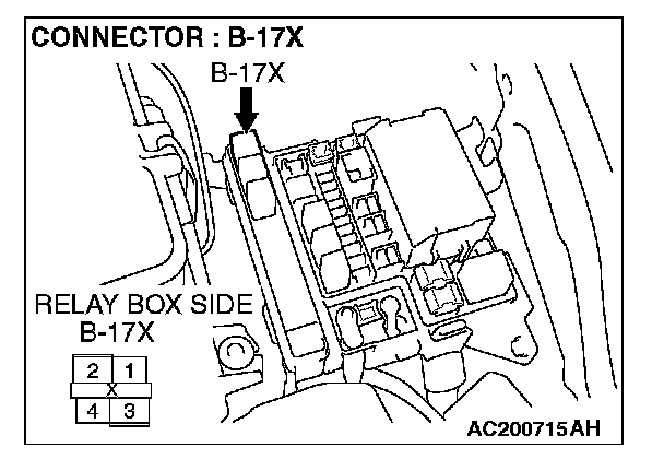
1. Disconnect A/C compressor connector B-17X and measure the voltage at the wiring harness side.
2. Measure the voltage between terminal 4 and ground.
- The measured value should be approximately 12 volts (battery positive voltage).
Q: Does the measured voltage correspond with this range?
YES: Go to Step 17.
NO: Go to Step 15.
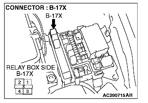
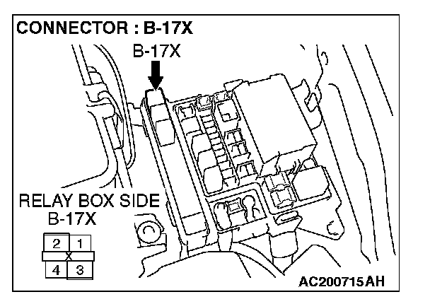
STEP 15. Check A/C compressor clutch relay connector B-17X for damage.
Q: Is A/C compressor clutch relay connector B-17X in good condition?
YES: Go to Step 16.
NO: Repair or replace the connector. Check that the air conditioning works normally.
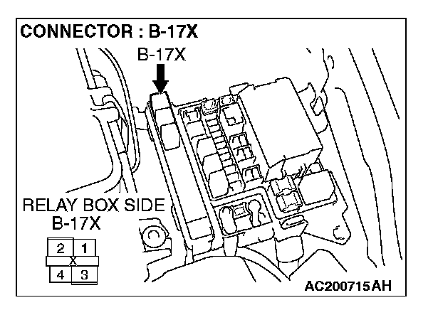
STEP 16. Check the wiring harness between A/C compressor clutch relay connector B-17X (terminal 4) and the battery.
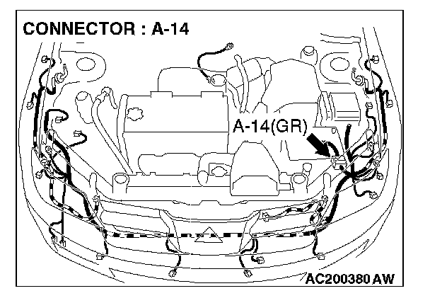
NOTE: Also check intermediate connector A-14. If intermediate connectors A-14 is damaged, repair or replace the connector as described in Harness Connector Inspection.
Q: Is the wiring harness between A/C compressor clutch relay connector B-17X (terminal 4) and the battery in good condition?
YES: Check that the air conditioning works normally.
NO: Repair the wiring harness. Check that the air conditioning works normally.

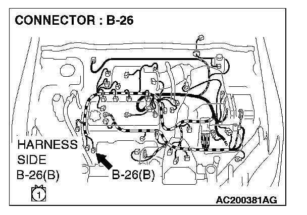
STEP 17. Check A/C compressor clutch relay connector B-17X and A/C compressor connector B-26 for damage.
Q: Is A/C compressor clutch relay connector B-17X and A/C compressor connector B-26 in good condition?
YES: Go to Step 18.
NO: Repair or replace the connector. Check that the air conditioning works normally.
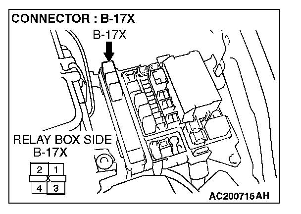
STEP 18. Check the wiring harness between A/C compressor clutch relay connector B-17X (terminal 1) and A/C compressor connector B-26 (terminal 1).
Q: Is the wiring harness between A/C compressor clutch relay connector B-17X (terminal 1) and A/C compressor connector B-26 (terminal 1) in good condition?
YES: Go to Step 19.
NO: Repair the wiring harness. Check that the air conditioning works normally.
STEP 19. Check engine control module
Q: Are engine control module
YES: Go to Step 20.
NO: Repair or replace the connector. Check that the air conditioning works normally.
STEP 20. Check the wiring harness between engine control module
Q: Is the wiring harness between engine control module
YES: Check that the air conditioning works normally.
NO: Repair the wiring harness. Check that the air conditioning works normally.
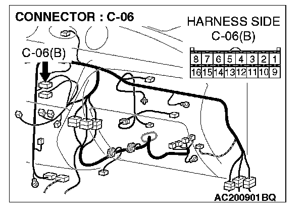
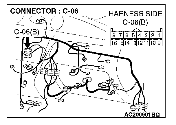
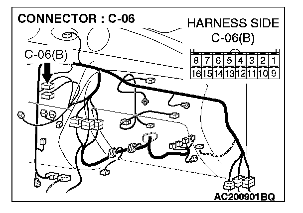
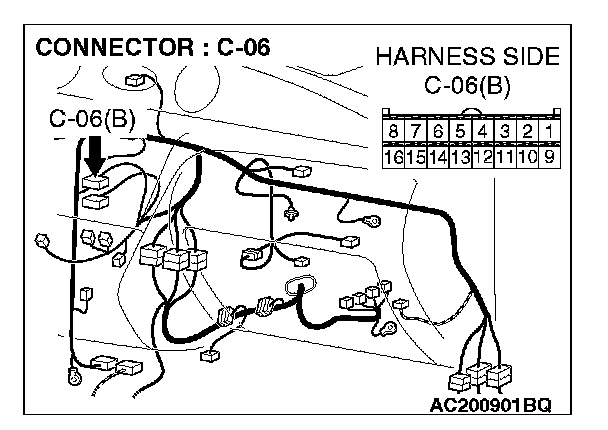
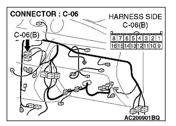
STEP 21. Measure the voltage at A/C-ECU connector C-06.
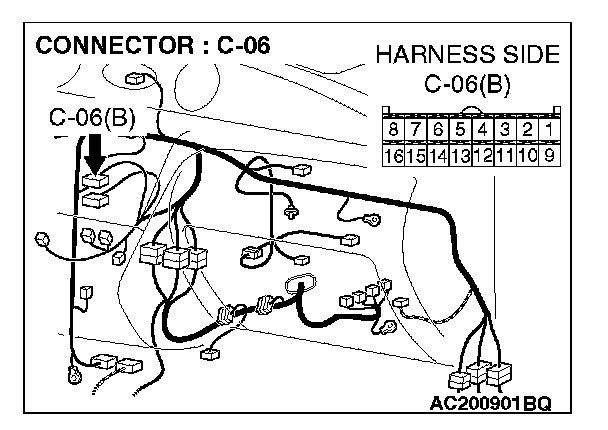
1. Disconnect A/C-ECU connector C-06 and measure the voltage at the relay box side.
2. Turn the ignition switch to the "ON" position.
3. Turn the A/C switch to the "ON" position.
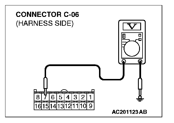
4. Measure the voltage between terminal 7 and ground.
- The measured value should be approximately 12 volts (battery positive voltage).
Q: Does the measured voltage correspond with this range?
YES: Go to Step 24.
NO: Go to Step 22.
STEP 22. Check A/C compressor clutch relay connector B-17X and A/C-ECU connector C-06 for damage.
Q: Are A/C compressor clutch relay connector B-17X and A/C-ECU connector C-06 in good condition?
YES: Go to Step 23.
NO: Repair or replace the connector. Check that the air conditioning works normally.
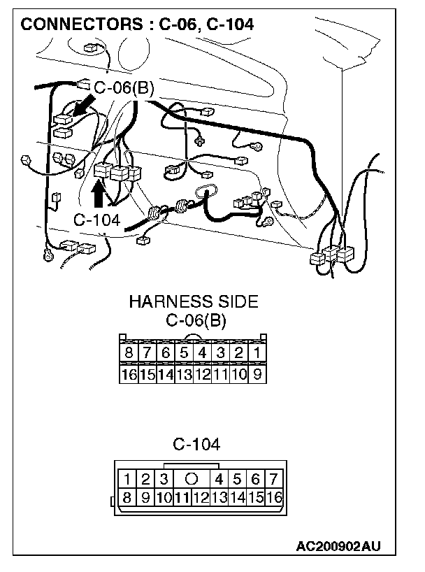
STEP 23. Check the wiring harness between A/C compressor clutch relay connector B-17X (terminal 1) and A/C-ECU connector C-06 (terminal 7).
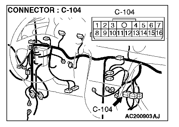
NOTE: Also check intermediate connector C-104. If intermediate connectors C-104 is damaged, repair or replace the connector as described in Harness Connector Inspection.
Q: Is the wiring harness between A/C compressor clutch relay connector B-17X (terminal 1) and A/C-ECU connector C-06 (terminal 7) in good condition?
YES: Check that the air conditioning works normally.
NO: Repair the wiring harness. Check that the air conditioning works normally.
STEP 24. Measure the voltage at A/C-ECU connector C-06.
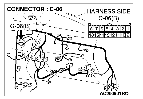
1. Disconnect A/C-ECU connector C-06 and measure the voltage at the relay box side.
2. Turn the ignition switch to the "ON" position.
3. Move the blower switch to the "HI" position.
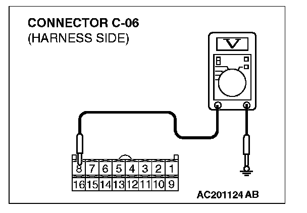
4. Measure the voltage between terminal 8 and ground.
- The measured value should be approximately 12 volts (battery positive voltage).
Q: Does the measured voltage correspond with this range?
YES: Go to Step 27.
NO: Go to Step 25.
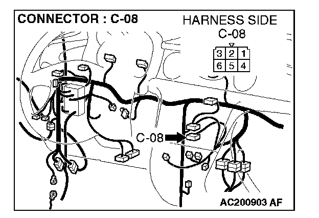
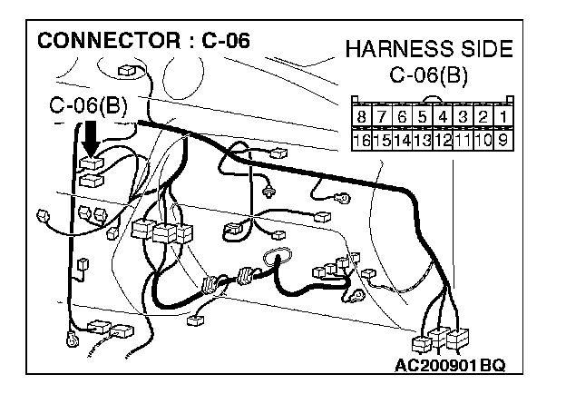
STEP 25. Check blower switch connector C-08 and A/C-ECU connector C-06 for damage.
Q: Is blower switch connector C-08 and A/C-ECU connector C-06 in good condition?
YES: Go to Step 26.
NO: Repair or replace the connector. Check that the air conditioning works normally.
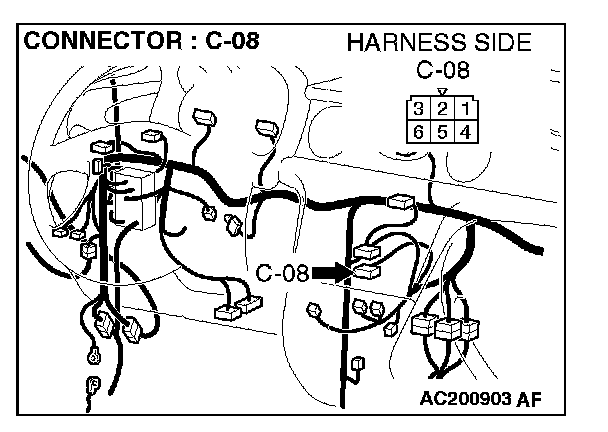

STEP 26. Check the wiring harness between blower switch connector C-08 (terminal 1) and A/C-ECU connector C-06 (terminal 8).
Q: Is the wiring harness between blower switch connector C-08 (terminal 1) and A/C-ECU connector C-06 (terminal 8) in good condition?
YES: Check that the air conditioning works normally.
NO: Repair the wiring harness. Check that the air conditioning works normally.
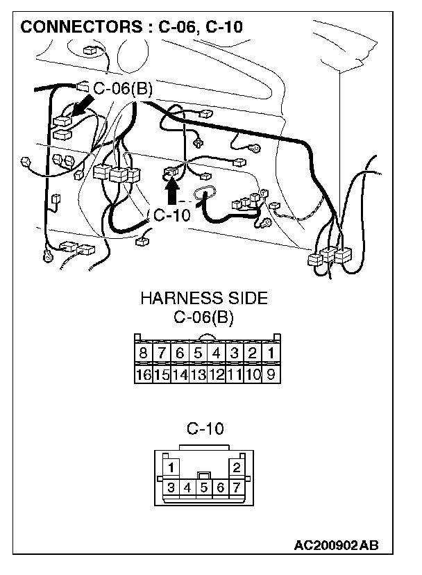
STEP 27. Check air thermo sensor connector C-10 and A/C-ECU connector C-06 for damage.
Q: Are air thermo sensor connector C-10 and A/C-ECU connector C-06 in good condition?
YES: Go to Step 28.
NO: Repair or replace the connector. Check that the air conditioning works normally.
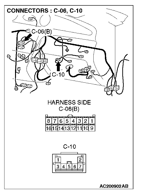
STEP 28. Check the wiring harness between air thermo sensor connector C-10 (terminals 1, 3, 4 and 5) and A/C-ECU connector C-06 (terminals 13, 14 and 16).
Q: Are the wiring harness between air thermo sensor connector C-10(terminals 1, 3, 4 and 5) and A/C-ECU connector C-06 (terminals 13, 14 and 16) in good condition?
YES: Go to Step 29.
NO: Repair the wiring harness. Check that the air conditioning works normally.
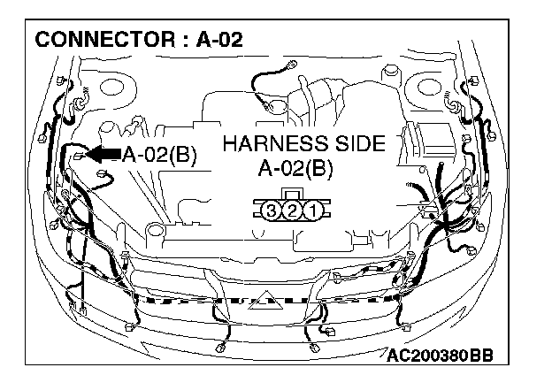
STEP 29. Check A/C pressure sensor connector A-02 and A/C-ECU connector C-06 for damage.
Q: Are A/C pressure sensor connector A-02 and A/C-ECU connector C-06 in good condition?
YES: Go to Step 30.
NO: Repair or replace the connector. Check that the air conditioning works normally.
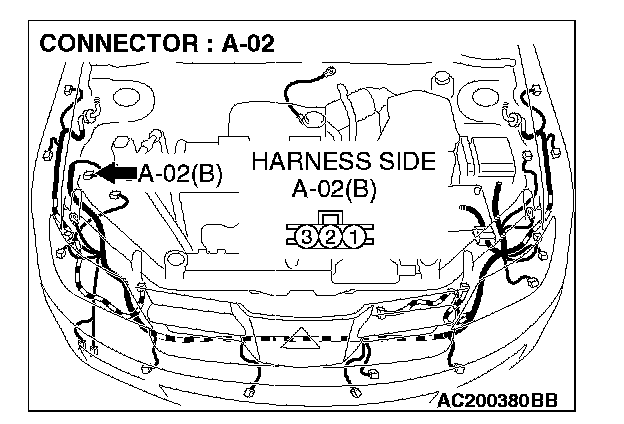
STEP 30. Check the wiring harness between A/C pressure sensor connector A-02 (terminal 2) and A/C-ECU connector C-06 (terminal 15).
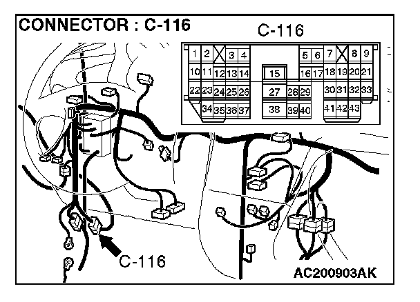
NOTE: Also check intermediate connector C-116. If intermediate connector C-116 is damaged, repair or replace the connector as described in Harness Connector Inspection.
Q: Are the wiring harness between A/C pressure sensor connector A-02 (terminal 2) and A/C-ECU connector C-06(terminal 15) in good condition?
YES: Go to Step 31.
NO: Repair the wiring harness. Check that the air conditioning works normally.
STEP 31. Check engine control module
Q: Are engine control module
YES: Go to Step 32.
NO: Repair or replace the connector. Check that the air conditioning works normally.
STEP 32. Check the wiring harness between engine control module
NOTE: Also check intermediate connector C-104. If intermediate connector C-104 is damaged, repair or replace the connector as described in Harness Connector Inspection.
Q: Are the wiring harness between engine control module
YES: Replace the A/C-ECU, engine control module
NO: Repair the wiring harness. Check that the air conditioning works normally.