Inspection Procedure 6
INSPECTION PROCEDURE 6: When Sunlight Intensity Changes, Blower Air Temperature does not Change.Photo Sensor Circuit Part 1:
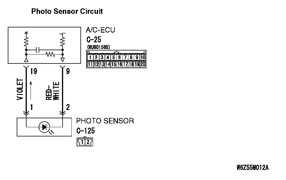
Photo Sensor Circuit Part 2:
CIRCUIT OPERATION
When the blower air temperature can not be changed even if the preset temperature is changed, the sensors may be defective.
TROUBLESHOOTING HINTS
- Malfunction of the photo sensor
- Malfunction of the A/C-ECU
- Damaged the wiring harness or connectors
DIAGNOSIS
Required Special Tools:
- MB991223: Harness Set
- MB992006: Extra Fine Probe
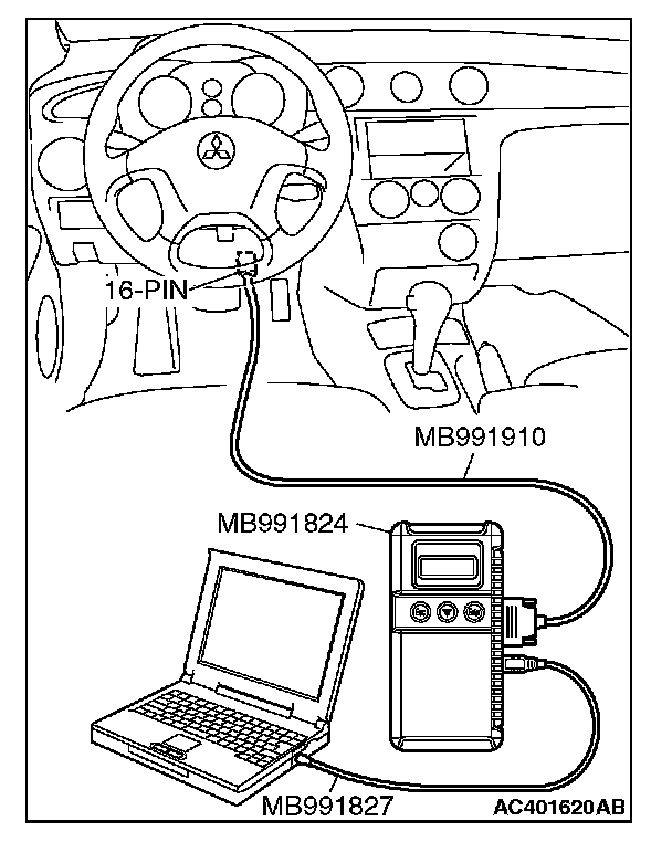
- MB991958: Scan Tool (MUT-III Sub Assembly)
- MB991824: Vehicle Communication Interface (V.C.I.)
- MB991827: MUT-III USB Cable
- MB991910: MUT-III Main Harness A (Vehicles with CAN communication system)
STEP 1. Check the rear window defogger and outside/inside air selection damper control motor operation.
Q: Do the rear window defogger and outside/inside air selection damper control motor work normally?
YES: Go to Step 2.
NO: Refer to Inspection procedure 10 "Malfunction of the A/C-ECU power supply system."
STEP 2. Using scan tool MB991958, read diagnostic trouble code.
CAUTION: To prevent damage to scan tool MB991958, always turn the ignition switch to the "LOCK" (OFF) position before connecting or disconnecting scan tool MB991958.
Check if an A/C-ECU DTC is set.
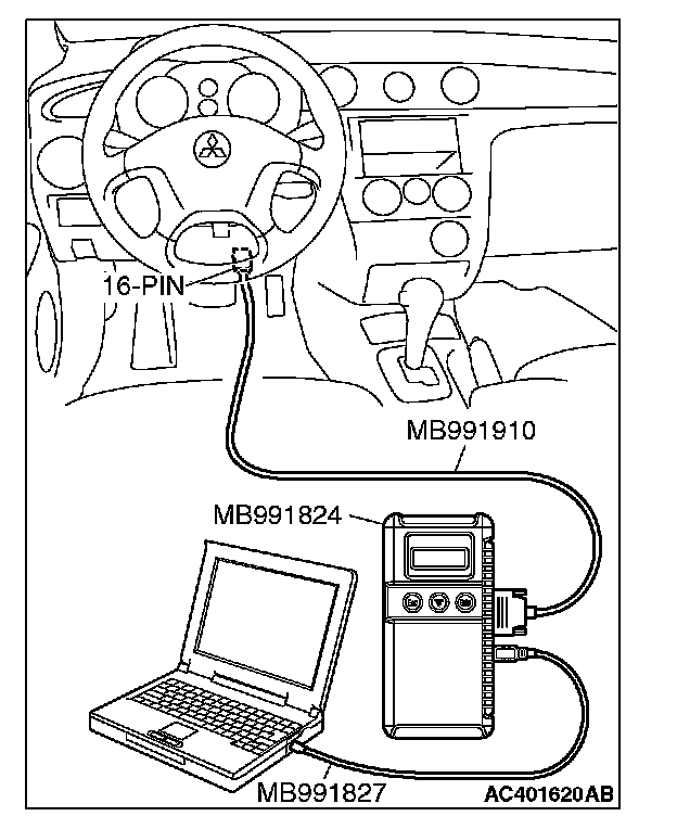
1. Connect scan tool MB991958 to the data link connector.
2. Turn the ignition switch to the "ON" position.
3. Check if the DTC is set.
4. Turn the ignition switch to the "LOCK" (OFF) position.
Q: Is the DTC set?
YES: Go to Step 3.
NO: Carry the diagnostic trouble code procedures.
STEP 3. Using scan tool MB991958, check data list.
1. Connect scan tool MB991958 to the data link connector.
2. Start the engine.
3. Set scan tool MB991958 to the data reading mode.
Item 25: Photo sensor.
- Check that the display on the scan tool changes when the photo sensor is covered with hands.
4. Turn the ignition switch to the "LOCK" (OFF) position.
Q: Is the sensor within the specified range?
YES: Replace the A/C-ECU.
NO: Go to Step 4.
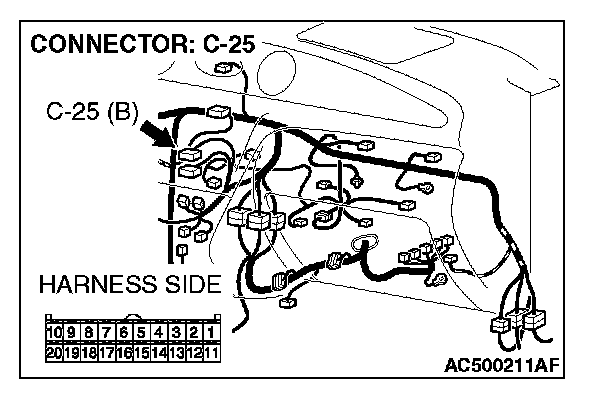
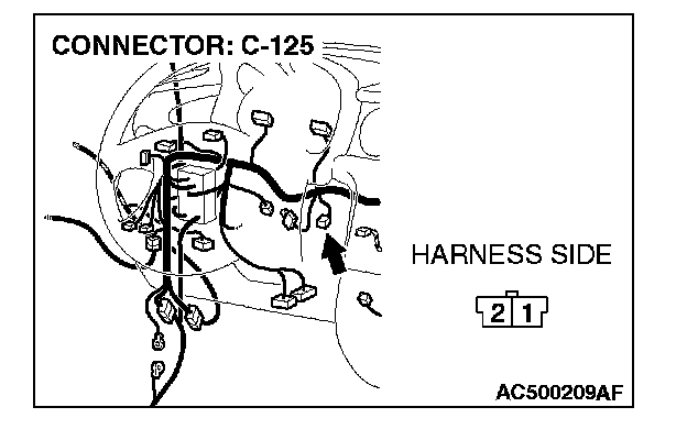
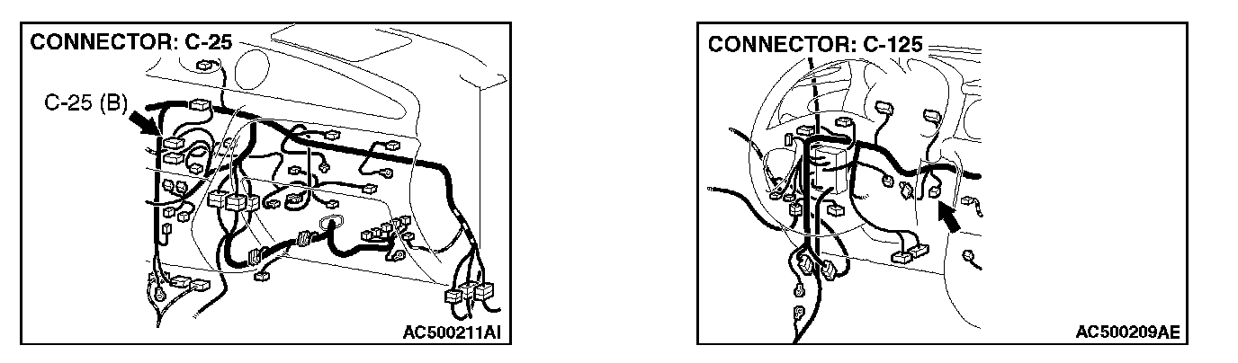
STEP 4. Check A/C-ECU connectors C-25 and photo sensor connector C-125 for loose, corroded or damaged terminals, or terminals pushed back in the connector.
Q: Are A/C-ECU connectors C-25 and photo sensor connector C-125 in good condition?
YES: Go to Step 5.
NO: Repair or replace the connector. Check that the air conditioning works normally.
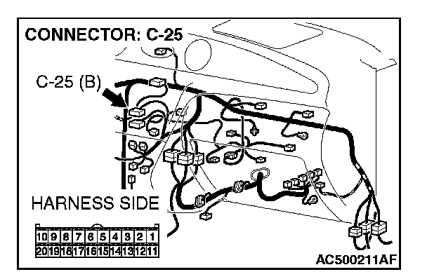
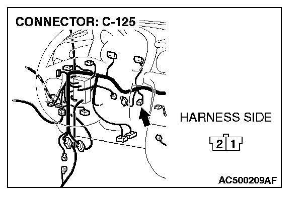
STEP 5. Check the wiring harness between A/C-ECU connector C-25 (terminal 9, 19) and photo sensor connector C-125 (terminal 2 and 1).
Q: Is the wiring harness between A/C-ECU connector C-25 (terminal 9, 19) and photo sensor connector C-125 (terminal 2 and 1) in good condition?
YES: Replace the photo sensor.
NO: Repair the wiring harness. Check that the air conditioning works normally.