Inspection Procedure 4
INSPECTION PROCEDURE 4: The Blower does not workBlower Linear Controller Circuit Part 1:
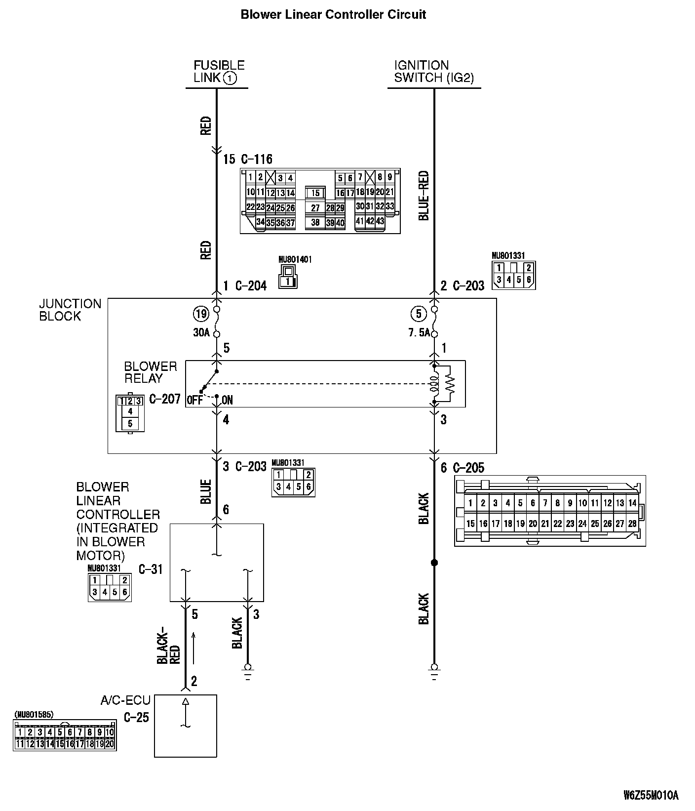
Blower Linear Controller Circuit Part 2:
CIRCUIT OPERATION
If the blower motor does not operate, the blower motor circuit system may be defective.
TROUBLESHOOTING HINTS
- Malfunction of the blower motor (blower linear controller).
- Malfunction of the A/C-ECU
- Damaged the wiring harness or connectors
DIAGNOSIS
Required Special Tools:
- MB991223: Harness Set
- MB992006: Extra Fine Probe
- MB991958: Scan Tool (MUT-III Sub Assembly)
- MB991824: Vehicle Communication Interface (V.C.I.)
- MB991827: MUT-III USB Cable
- MB991910: MUT-III Main Harness A
STEP 1. Using scan tool MB991958, read the diagnostic trouble code.
CAUTION: To prevent damage to scan tool MB991958, always turn the ignition switch to the "LOCK" (OFF) position before connecting or disconnecting scan tool MB991958.
Check if an A/C-ECU DTC is set.
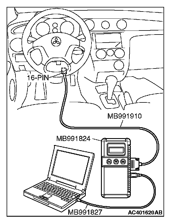
1. Connect scan tool MB991958 to the data link connector.
2. Turn the ignition switch to the "ON" position.
3. Check if the DTC is set.
4. Turn the ignition switch to the "LOCK" (OFF) position.
Q: Is the check result satisfactory?
YES: Refer to Diagnostic Trouble Code Chart. Diagnostic Trouble Code Descriptions
NO: Go to Step 2.
STEP 2. Using scan tool MB991958, check actuator test.
1. Connect scan tool MB991958 to the data link connector.
2. Start the engine.
3. Use scan tool MB991958 to run the actuator test.
- Item 01: Blower fan: OFF
- Item 02: Blower fan: Low speed
- Item 03: Blower fan: Middle speed
- Item 04: Blower fan: High speed
- Check that the blower motor operates.
4. Turn the ignition switch to the "LOCK" (OFF) position.
Q: Does the motor operate normally?
YES: Replace the A/C-ECU.
NO: Go to Step 3.
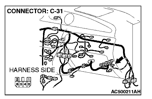
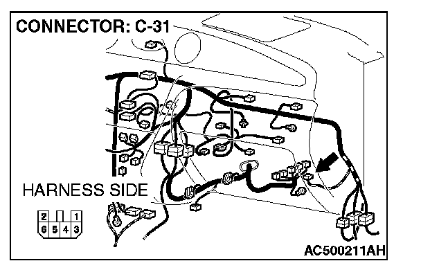
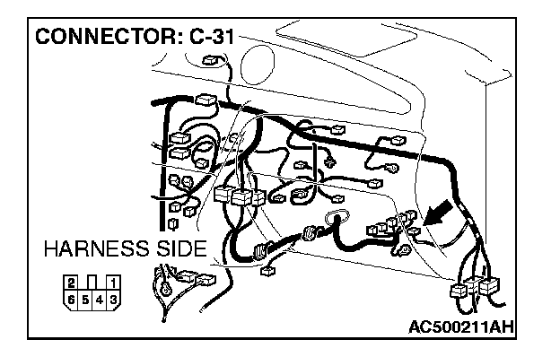
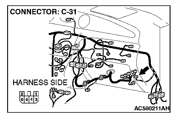
STEP 3. Measure the voltage at blower linear controller connector C-31.
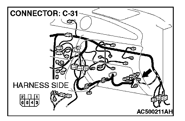
1. Disconnect blower linear controller connector C-31, and measure the voltage at the wiring harness side.
2. Turn the ignition switch to the "ON" position.
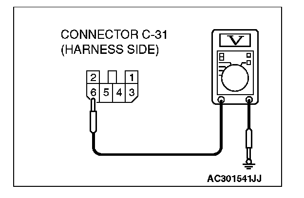
3. Measure the voltage between terminal 6 and ground.
- The measured value should be approximately 12 volts (battery positive voltage).
Q: Is the measured voltage approximately 12 volts?
YES: Go to Step 16.
NO: Go to Step 4.
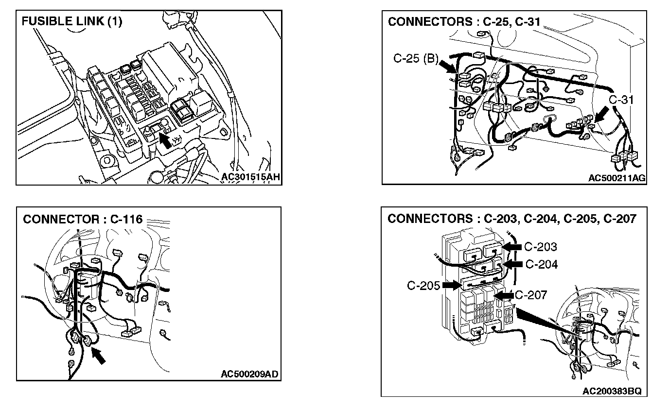
STEP 4. Check the blower relay. Refer to Heating and Air Conditioning On-vehicle Service - Power relay check.
Q: Is the blower relay in good condition?
YES: Go to Step 5.
NO: Replace the blower relay.
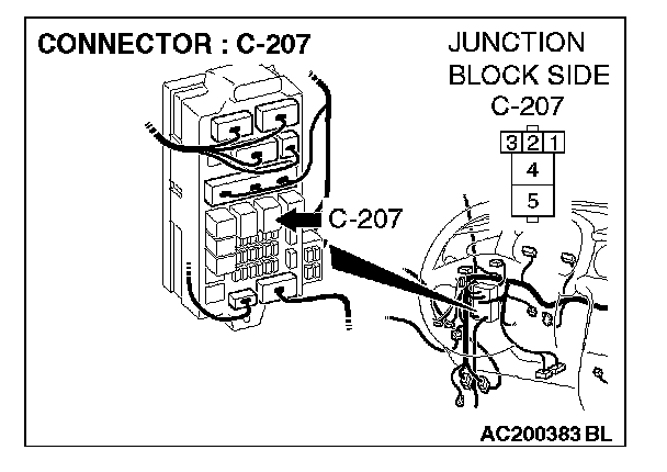
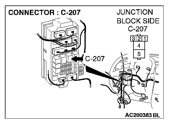
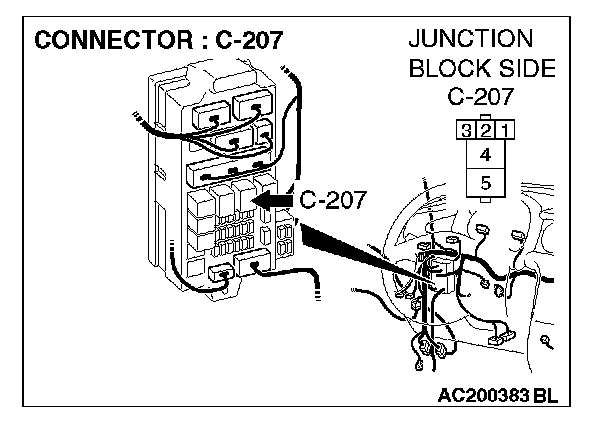
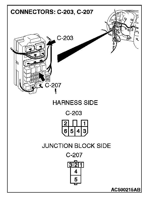
STEP 5. Measure the voltage at blower relay connector C-207.
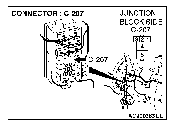
1. Disconnect blower relay connector C-207, and measure the voltage at the junction block side.
2. Turn the ignition switch to the "ON" position.
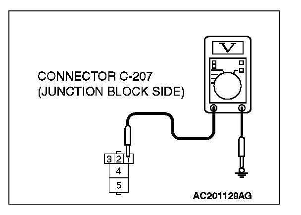
3. Measure the voltage between terminal 1 and ground.
- The measured value should be approximately 12 volts (battery positive voltage).
Q: Does the measured voltage correspond with this range?
YES: Go to Step 8.
NO: Go to Step 6.
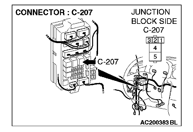
STEP 6. Check blower relay connector C-207 for damage.
Q: Is blower relay connector C-207 in good condition?
YES: Go to Step 7.
NO: Repair the connector.
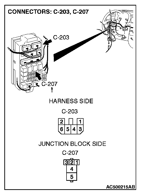
STEP 7. Check the wiring harness between blower relay connector C-207 (terminal 1) and the ignition switch (IG2).
NOTE: Also check junction block connector C-203. If junction block connector C-203 is damaged, repair or replace the connector as described in Harness Connector Inspection.
Q: Is the wiring harness between blower relay connector C-207 (terminal 1) and the ignition switch (IG2) in good condition?
YES: The blower motor should operate normally.
NO: Repair the wiring harness. The blower motor should operate normally.
STEP 8. Measure the voltage at blower relay connector C-207.

1. Disconnect blower relay connector C-207, and measure the voltage at the junction block side.
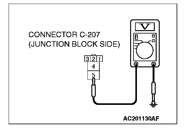
2. Measure the voltage between terminal 5 and ground.
- The measured value should be approximately 12 volts (battery positive voltage).
Q: Does the measured voltage correspond with this range?
YES: Go to Step 11.
NO: Go to Step 9.
STEP 9. Check blower relay connector C-207 for damage.
Q: Is blower relay connector C-207 in good condition?
YES: Go to Step 10.
NO: Repair the connector.
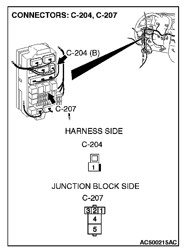
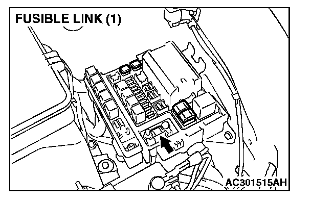
STEP 10. Check the wiring harness between blower relay connector C-207 (terminal 5) and fusible link (1).
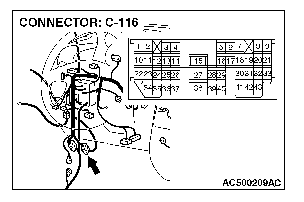
NOTE: Also check intermediate connector C-116 and junction block connector C-204. If intermediate connector C-116 or junction block connector C-204 is damaged, repair or replace the connector as described in Harness Connector Inspection.
Q: Is the wiring harness between blower relay connector C-207 (terminal 5) and fusible link 1. in good condition?
YES: The blower motor should operate normally.
NO: Repair the wiring harness. The blower motor should operate normally.
STEP 11. Measure the resistance at blower relay connector C-207 in order to the ground circuit to the blower relay.
1. Disconnect connector C-207, and measure the resistance at the junction block side.
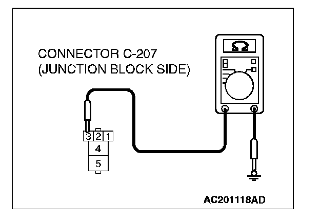
2. Measure the resistance value between terminal 3 and ground.
- The measured value should be 2 ohms or less.
Q: Does the measured resistance value correspond with this range?
YES: Go to Step 14.
NO: Go to Step 12.

STEP 12. Check blower relay connector C-207 for damage.
Q: Is blower relay connector C-207 in good condition?
YES: Go to Step 13.
NO: Repair the connector.
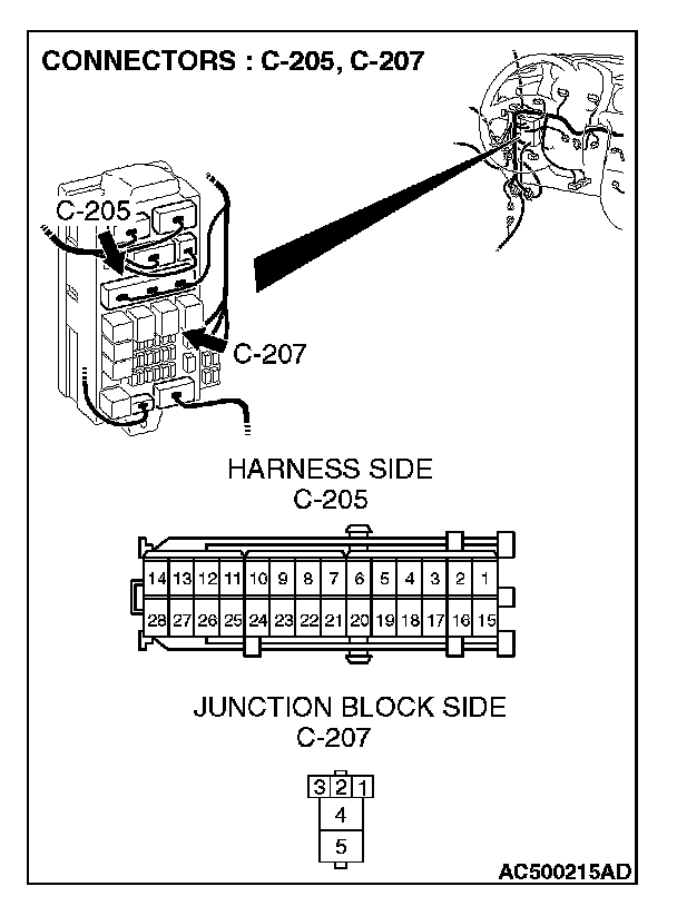
STEP 13. Check the wiring harness between blower relay connector C-207 (terminal 3) and ground.
NOTE: Also check junction block connector C-205. If junction block connector C-205 is damaged, repair or replace the connector as described in Harness Connector Inspection.
Q: Is the wiring harness between blower relay connector C-207 (terminal 3) and ground in good condition?
YES: The blower motor should operate normally.
NO: Repair the wiring harness. The blower motor should operate normally.
STEP 14. Check blower linear controller connector C-31 and blower relay connector C-207 for loose, corroded or damaged terminals, or terminals pushed back in the connector.
Q: Are blower linear controller connector C-31 and blower relay connector C-207 in good condition?
YES: Go to Step 15.
NO: Repair or replace the connector. Check that the air conditioning works normally.
STEP 15. Check the wiring harness between blower linear controller connector C-31 (terminal 6) and blower relay connector C-207 (terminal 4).
NOTE: Also check junction block connector C-203 for loose, corroded, or damaged terminals, or terminals pushed back in the connector. If junction block connector C-203 is damaged, repair or replace the connector as described in Harness Connector Inspection.
Q: Is the wiring harness between blower linear controller connector C-31 (terminal 6) and blower relay connector C-207 (terminal 4) in good condition?
YES: It can be assumed that this malfunction is intermittent. Refer to How to Use Troubleshooting/Inspection Service Points- How to Cope with Intermittent Malfunctions.
NO: Repair the wiring harness. The blower motor should operate normally.
STEP 16. Measure the resistance at blower linear controller connector C-31 in order to the ground circuit to the blower motor.
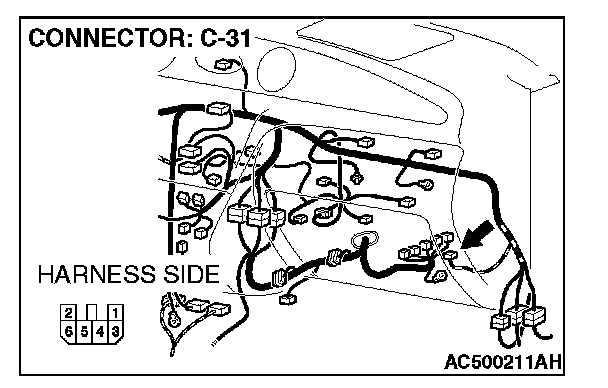
1. Disconnect blower linear controller connector C-31, and measure the resistance at the wiring harness side.
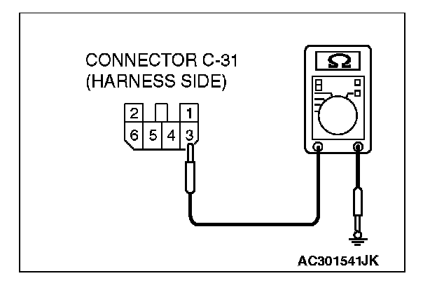
2. Measure the resistance value between terminal 3 and ground.
- The measured value should be 2 Ohms or less.
Q: Does the measured resistance value correspond with this range?
YES: Go to Step 19.
NO: Go to Step 17.
STEP 17. Check blower linear controller connector C-31 for damage.
Q: Is blower linear controller connector C-31 in good condition?
YES: Go to Step 18.
NO: Repair or replace the connector. Check that the air conditioning works normally.
STEP 18. Check the wiring harness between blower linear controller connector C-31 (terminal 3) and ground.
Q: Is the wiring harness between blower linear controller connector C-31 (terminal 3) and ground in good condition?
YES: It can be assumed that this malfunction is intermittent. Refer to How to Use Troubleshooting/Inspection Service Points- How to Cope with Intermittent Malfunctions.
NO: Repair the wiring harness. The blower motor should operate normally.
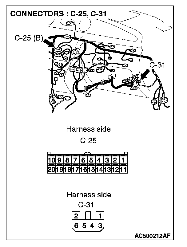
STEP 19. Check A/C-ECU connector C-25 and blower linear controller connector C-31 for damage.
Q: Is A/C-ECU connector C-25 and blower linear controller connector C-31 in good condition?
YES: Go to Step 20.
NO: Repair or replace the connector. Check that the air conditioning works normally.
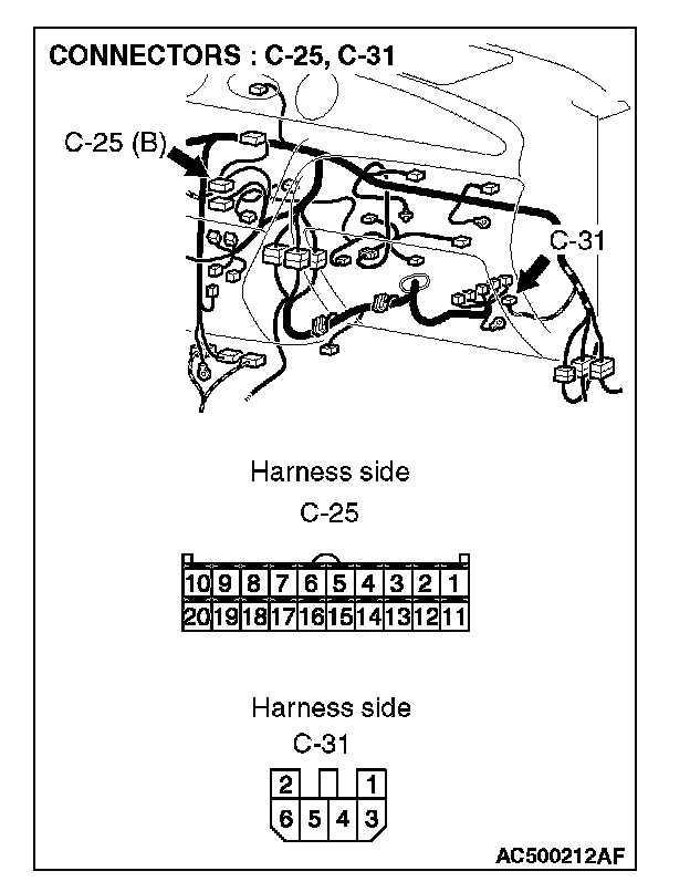
STEP 20. Check the wiring harness between A/C-ECU connector C-25 (terminal 2) and blower linear controller connector C-31 (terminal 5).
Q: Is the wiring harness between A/C-ECU connector C-25 (terminal 2) and blower linear controller connector C-31 (terminal 5) in good condition?
YES: Replace the A/C-ECU or the blower motor.
NO: Repair the wiring harness. The blower motor should operate normally.