Inspection Procedure 2
INSPECTION PROCEDURE 2: The Air Conditioning does not work at allA/C Compressor Circuit Part 1:
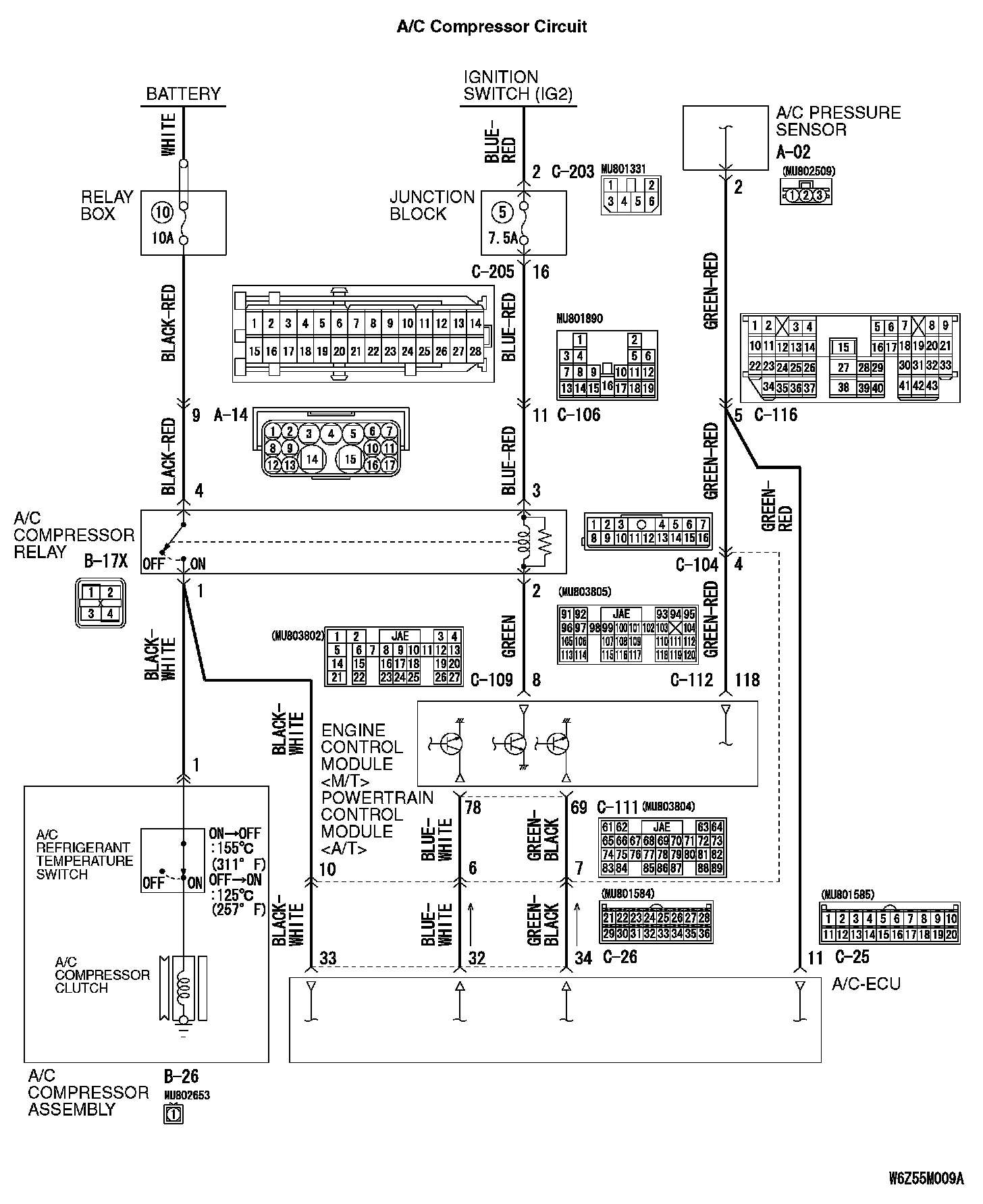
A/C Compressor Circuit Part 2:
CIRCUIT OPERATION
If cool air is not distributed when the A/C switch is on, A/C compressor relay system may be defective.
TROUBLESHOOTING HINTS
- Improper amount of refrigerant
- Malfunction of the A/C pressure sensor
- Malfunction of the A/C compressor relay
- Malfunction of the magnetic clutch
- Malfunction of the A/C refrigerant temperature switch
- Damaged the wiring harness or connectors
- Malfunction of the A/C-ECU
DIAGNOSIS
Required Special Tools:
- MB991223: Harness Set
- MB992006: Extra Fine Probe
- MB991958: Scan Tool (MUT-III Sub Assembly)
- MB991824: Vehicle Communication Interface (V.C.I.)
- MB991827: MUT-III USB Cable
- MB991910: MUT-III Main Harness A (Vehicles with CAN communication system)
STEP 1. Use the scan tool MB991958 to confirm a diagnostic trouble code.
On completion, check that the diagnostic trouble code is not reset.
Q: Is the check result normal?
YES: Go to Step 2.
NO: Refer to diagnostic trouble code chart. Diagnostic Trouble Code Descriptions
STEP 2. Check the blower operation.
1. Turn the ignition switch to the ON position.
2. Blower knob: Other than OFF
3. Check that the air comes out of the blower.
Q: Is the check result normal?
YES: Go to Step 3.
NO: Refer to Inspection Procedure 4 "The blower does not work."
STEP 3. Check the rear window defogger and outside/inside air selection damper control motor operation.
Q: Do the defogger and outside/inside air selection damper control motor work normally?
YES: Go to Step 4.
NO: Refer to Inspection procedure 10 "Malfunction of the A/C-ECU power supply system"
STEP 4. Check the A/C compressor. Check the A/C compressor for compressor oil leaks.
Q: Is the check result satisfactory?
YES: Go to Step 5.
NO: Replace the A/C compressor or the expansion valve.
STEP 5. Measure the voltage at A/C compressor connector B-26.

1. Disconnect the connector, and measure at the wiring harness side.
2. Turn the ignition switch to the "ON" position.
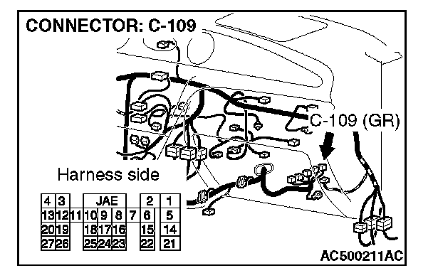
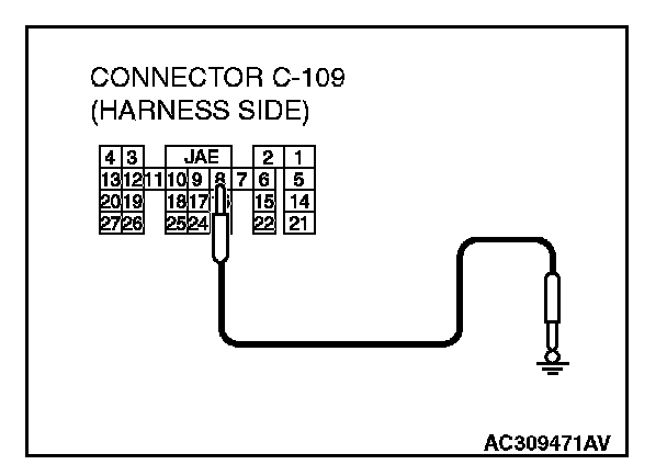
3. Disconnect power control module connector C-109 and ground terminal 8.
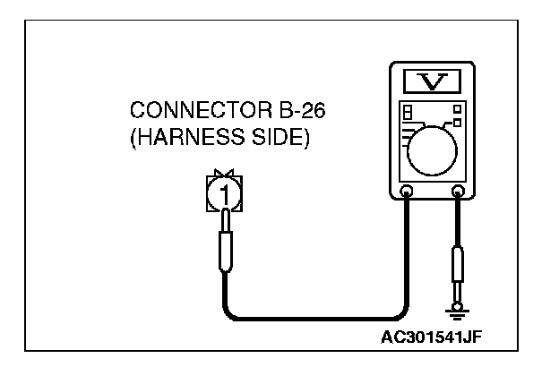
4. Measure the voltage between terminal 1 and ground.
- The measured value should be approximately 12 volts (battery positive voltage).
Q: Is the check result normal?
YES: Go to Step 17.
NO: Go to Step 6.
STEP 6. Check the A/C compressor relay continuity. Refer to On-vehicle service, power relay in Heating and Air Conditioning.
Q: Is the A/C compressor relay in good condition?
YES: Go to Step 7.
NO: Replace the A/C compressor relay.
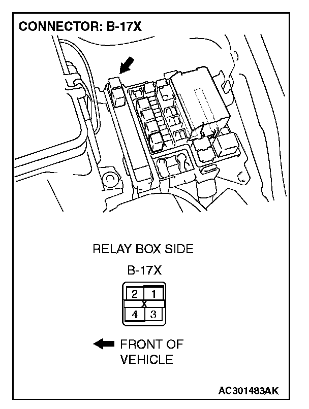
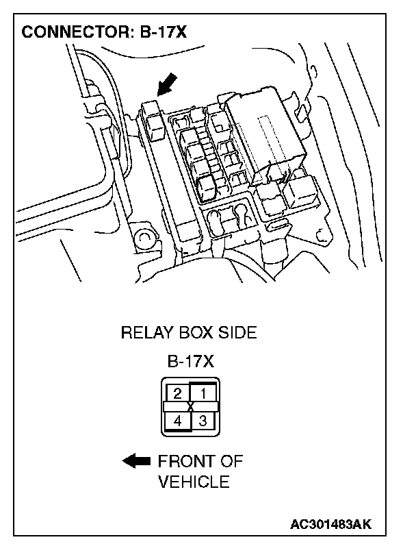
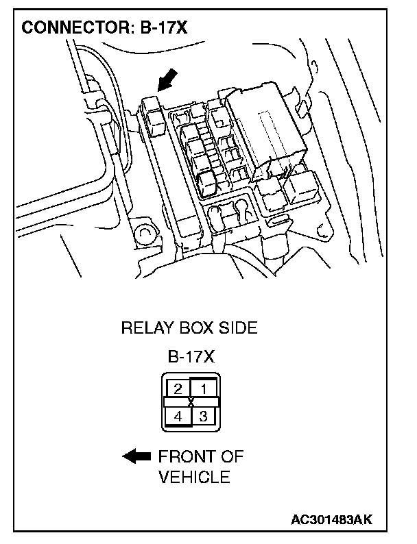
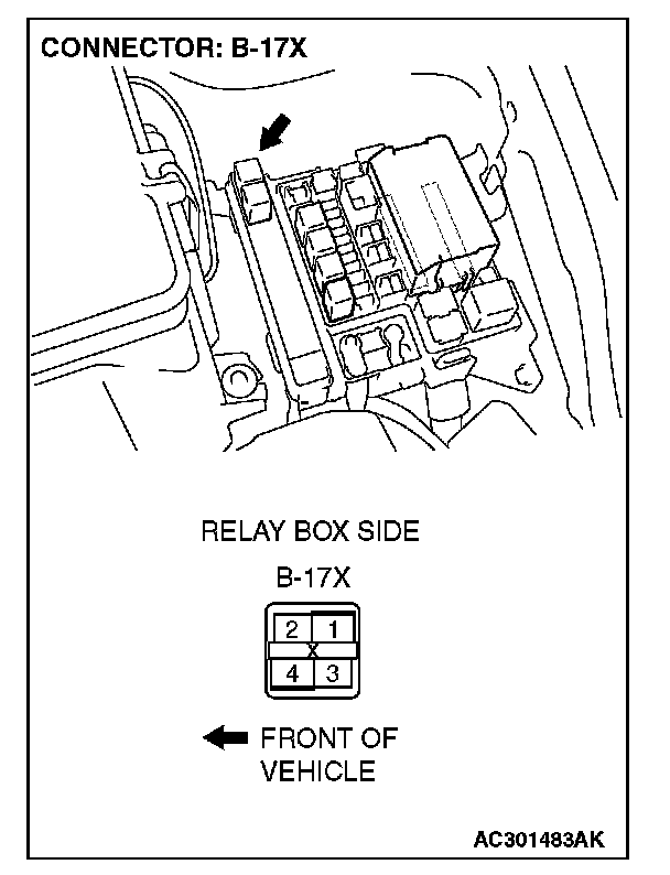
STEP 7. Measure the voltage at A/C compressor relay connector B-17X.

1. Remove the relay, and measure at the relay block side.
2. Turn the ignition switch to the "ON" position.
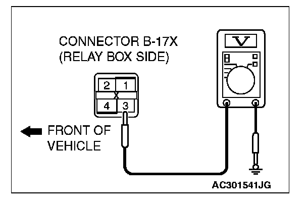
3. Measure the voltage between terminal 3 and ground.
- The measured value should be approximately 12 volts (battery positive voltage).
Q: Does the measured voltage correspond with this range?
YES: Go to Step 10.
NO: Go to Step 8.
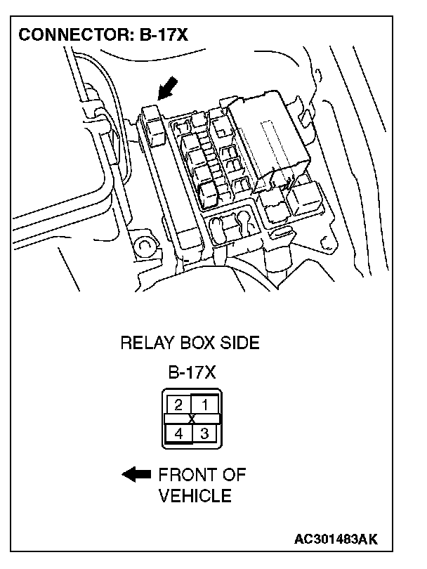
STEP 8. Check A/C compressor relay connector B-17X for damage.
Q: Is A/C compressor relay connector B-17X in good condition?
YES: Go to Step 9.
NO: Repair or replace the connector. Check that the air conditioning works normally.
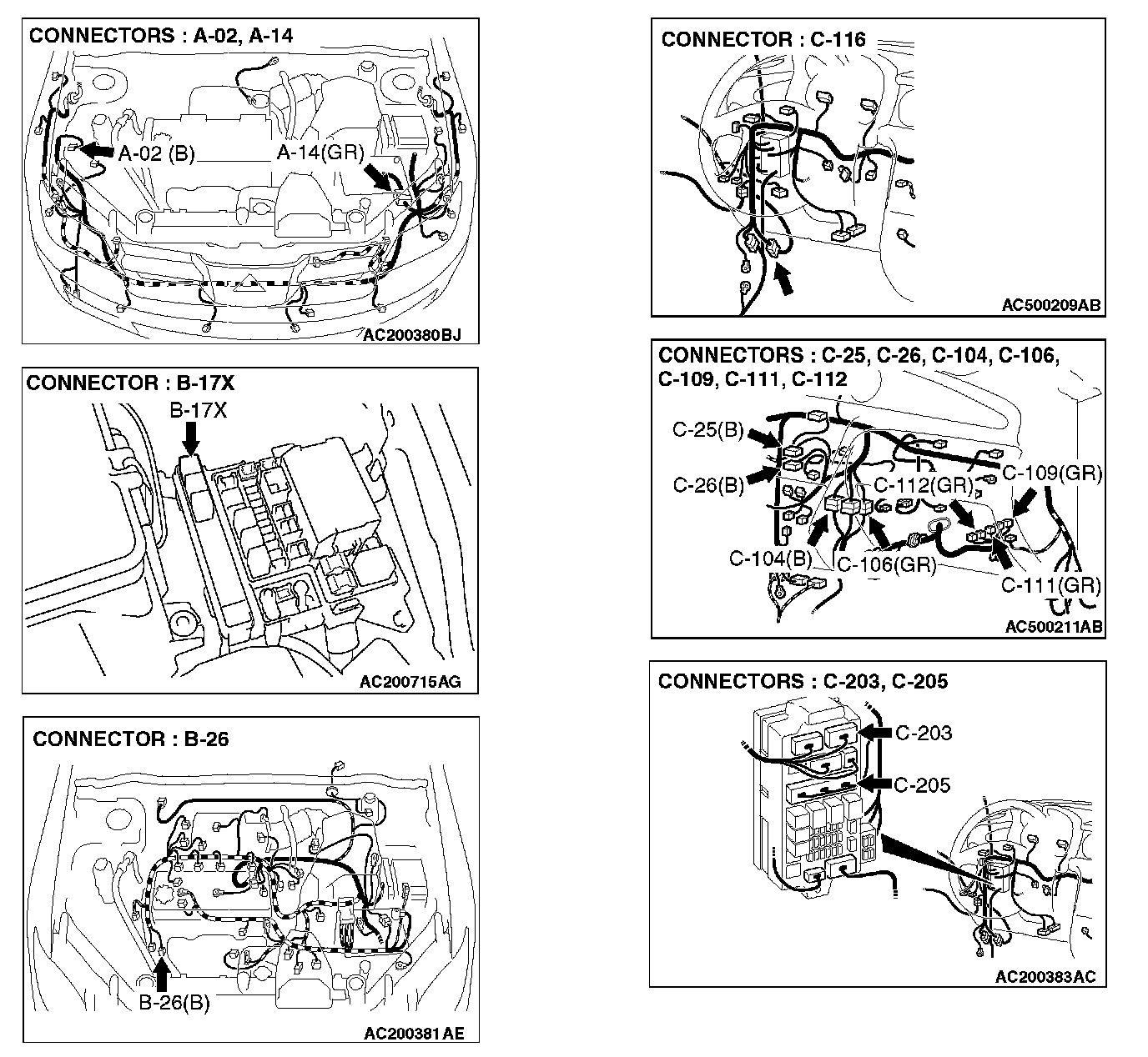
STEP 9. Check the wiring harness between A/C compressor relay connector B-17X (terminal 3) and the ignition switch (IG2).
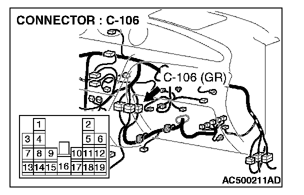
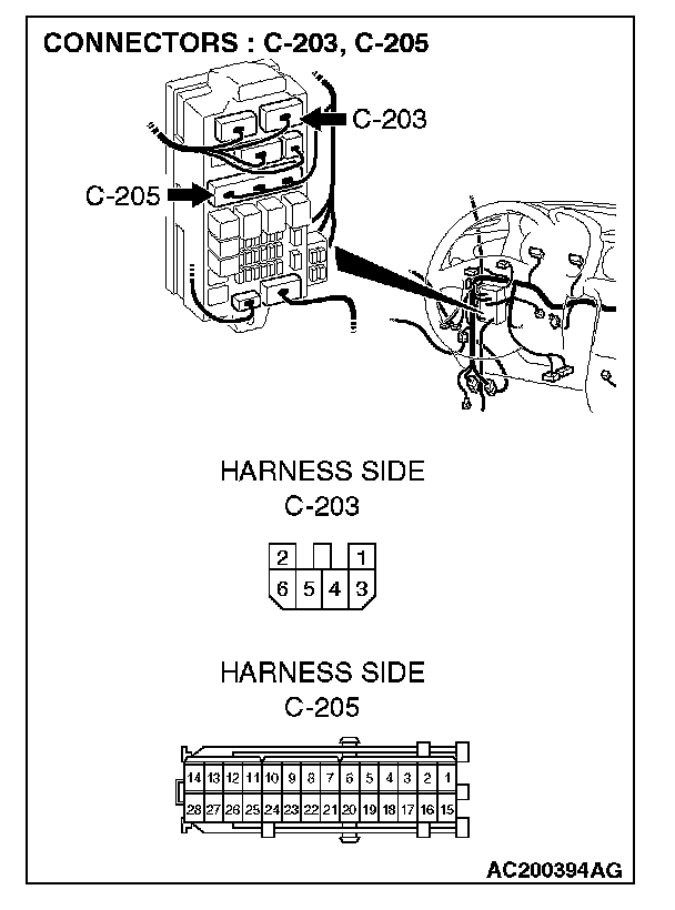
NOTE: Also check intermediate connector C-106, junction block connectors C-205 and C-203. If intermediate connector C-106 or junction block connectors C-205 or C-203 is damaged, repair or replace the connector as described in Harness Connector Inspection.
Q: Is the wiring harness between A/C compressor clutch relay connector B-17X (terminal 3) and the ignition switch (IG2) in good condition?
YES: Check that the air conditioning works normally.
NO: Repair the wiring harness. Check that the air conditioning works normally.
STEP 10. Measure the voltage at A/C compressor clutch relay connector B-17X.
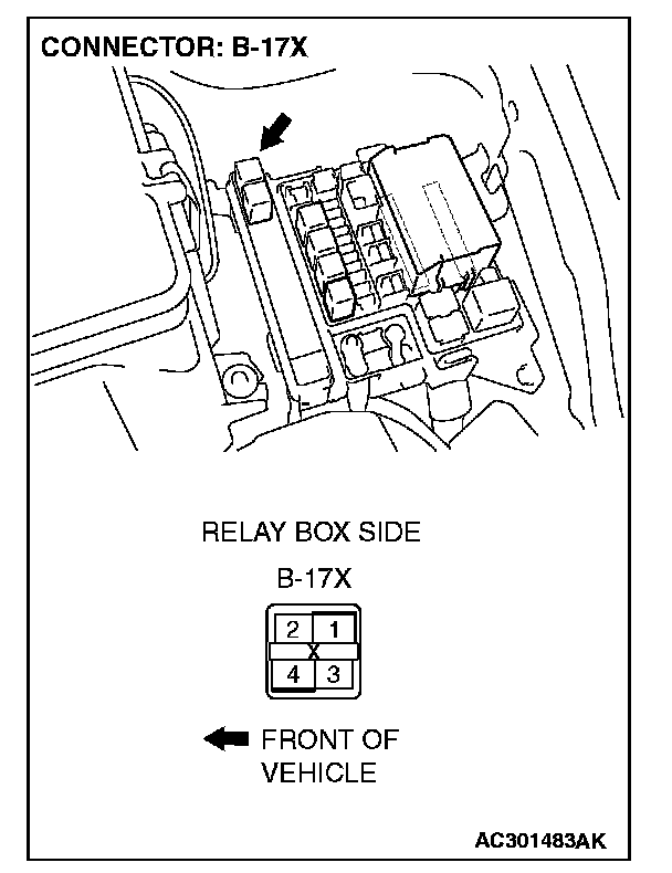
1. Disconnect A/C compressor connector B-17X and measure the voltage at the wiring harness side.
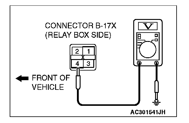
2. Measure the voltage between terminal 4 and ground.
- The measured value should be approximately 12 volts (battery positive voltage).
Q: Does the measured voltage correspond with this range?
YES: Go to Step 13.
NO: Go to Step 11.

STEP 11. Check A/C compressor relay connector B-17X for damage.
Q: Is A/C compressor relay connector B-17X in good condition?
YES: Go to Step 12.
NO: Repair or replace the connector. Check that the air conditioning works normally.

STEP 12. Check the wiring harness between A/C compressor relay connector B-17X (terminal 4) and the battery.
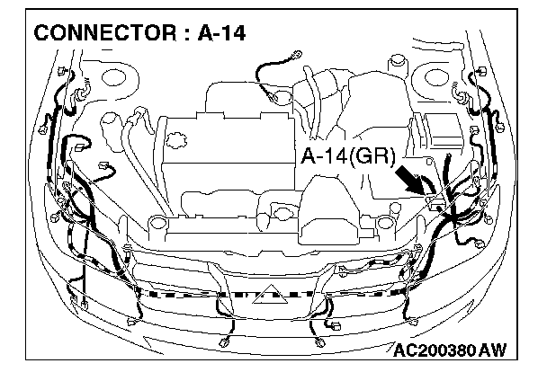
NOTE: Also check intermediate connector A-14. If intermediate connectors A-14 is damaged, repair or replace the connector as described in Harness Connector Inspection.
Q: Is the wiring harness between A/C compressor relay connector B-17X (terminal 4) and the battery in good condition?
YES: Check that the air conditioning works normally.
NO: Repair the wiring harness. Check that the air conditioning works normally.

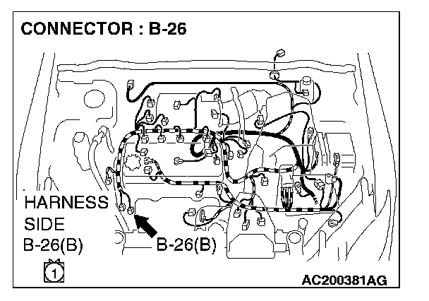
STEP 13. Check A/C compressor relay connector B-17X and A/C compressor connector B-26 for damage.
Q: Is A/C compressor relay connector B-17X and A/C compressor connector B-26 in good condition?
YES: Go to Step 14.
NO: Repair or replace the connector. Check that the air conditioning works normally.
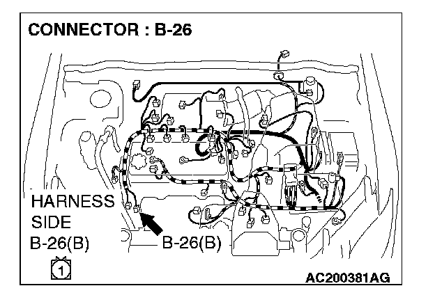
STEP 14. Check the wiring harness between A/C compressor relay connector B-17X (terminal 1) and A/C compressor connector B-26 (terminal 1).
Q: Is the wiring harness between A/C compressor relay connector B-17X (terminal 1) and A/C compressor connector B-26 (terminal 1) in good condition?
YES: Go to Step 15.
NO: Repair the wiring harness. Check that the air conditioning works normally.

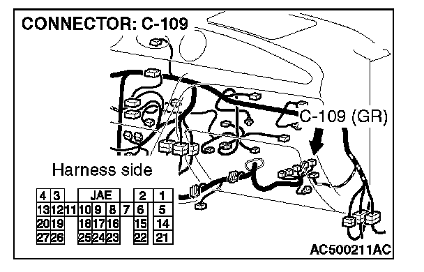
STEP 15. Check powertrain control module connector C-109 and A/C compressor relay connector B-17X for damage.
Q: Are powertrain control module connector C-109 and A/C compressor relay connector B-17X in good condition?
YES: Go to Step 16.
NO: Repair or replace the connector. Check that the air conditioning works normally.
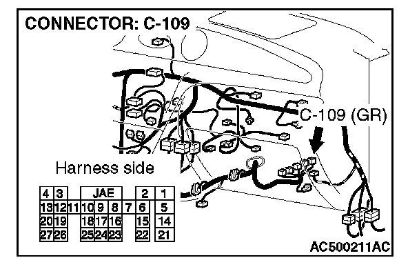
STEP 16. Check the wiring harness between powertrain control module connector C-109 (terminal 8) and A/C compressor relay connector B-17X (terminal 2).
Q: Is the wiring harness between powertrain control module connector C-109 (terminal 8) and A/C compressor clutch relay connector B-17X (terminal 2) in good condition?
YES: Check that the air conditioning works normally.
NO: Repair the wiring harness. Check that the air conditioning works normally.
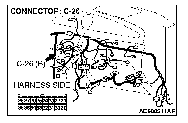
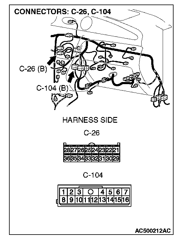
STEP 17. Measure the voltage at A/C-ECU connector C-26.
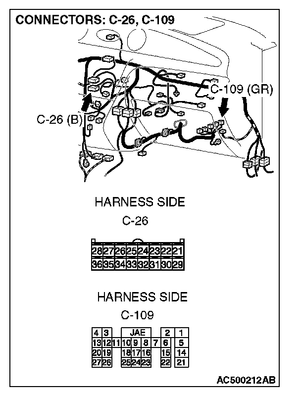
1. Disconnect A/C-ECU connector C-26 and measure the voltage at the relay box side.
2. Turn the ignition switch to the "ON" position.
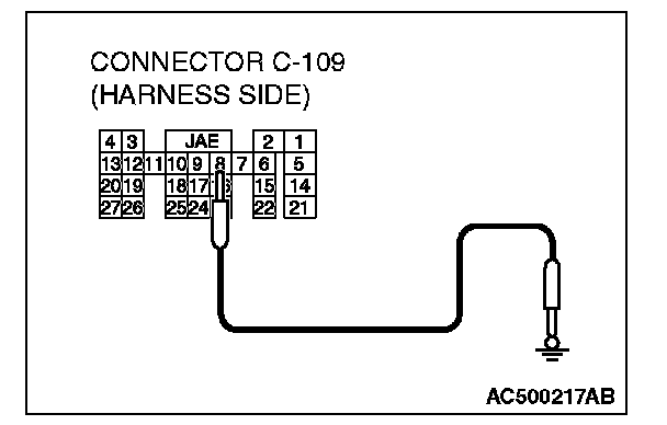
3. Disconnect powertrain control module connector C-109 and ground terminal 8.
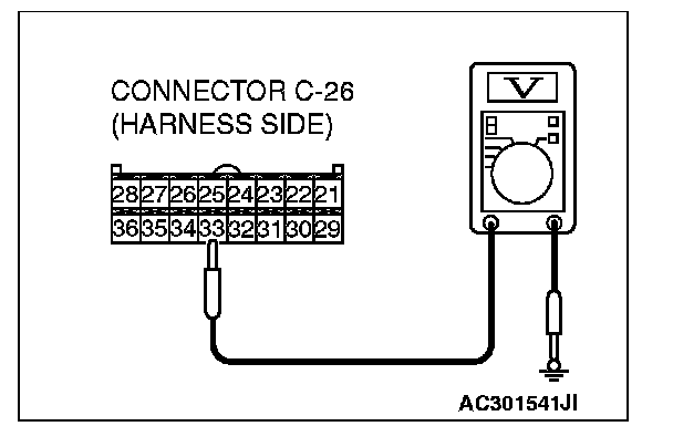
4. Measure the voltage between terminal 33 and ground.
- The measured value should be approximately 12 volts (battery positive voltage).
Q: Is the check result normal?
YES: Go to Step 20.
NO: Go to Step 18.

STEP 18. Check A/C compressor relay connector B-17X and A/C-ECU connector C-26 for damage.
Q: Are A/C compressor relay connector B-17X and A/C-ECU connector C-26 in good condition?
YES: Go to Step 19.
NO: Repair or replace the connector. Check that the air conditioning works normally.
STEP 19. Check the wiring harness between A/C compressor relay connector B-17X (terminal 1) and A/C-ECU connector C-26 (terminal 33).
NOTE: Also check intermediate connector C-104. If intermediate connectors C-104 is damaged, repair or replace the connector as described in Harness Connector Inspection.
Q: Is the wiring harness between A/C compressor relay connector B-17X (terminal 1) and A/C-ECU connector C-26 (terminal 33) in good condition?
YES: Check that the air conditioning works normally.
NO: Repair the wiring harness. Check that the air conditioning works normally.
STEP 20. Check the A/C compressor clutch operation.
Q: Can the sound of the A/C compressor clutch (click) be heard?
YES: Go to Step 21.
NO: Replace the compressor magnet clutch.
STEP 21. Check the refrigerant temperature switch.
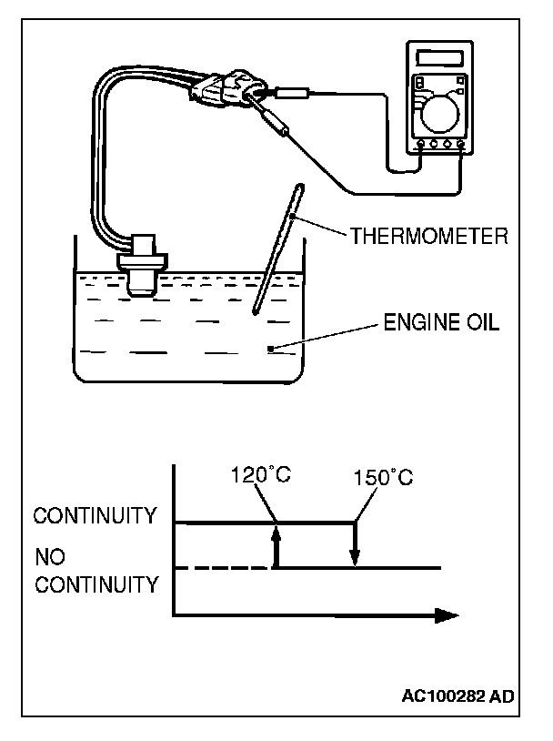
1. Immerse the refrigerant temperature sensor probe into heated engine oil to heat the sensor probe.
CAUTION: Do not heat the sensor probe more than necessary.
2. When the oil temperature reaches the standard value, check that voltage is supplied between the terminals.
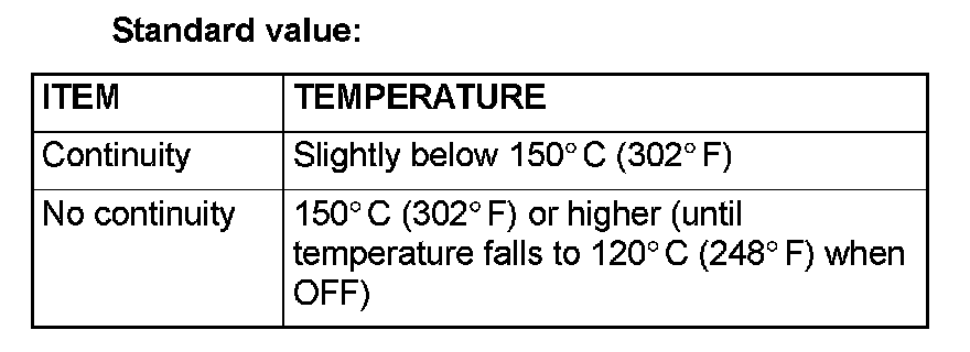
Standard value:
Q: Is the refrigerant temperature switch operating properly?
YES: Go to Step 22.
NO: Replace the refrigerant temperature switch.
STEP 22. Check the refrigerant level.
Q: Is the refrigerant level correct?
YES: Go to Step 23.
NO: Correct the refrigerant level (Refer to tire and wheel On-vehicle Service).
STEP 23. Check the A/C pressure sensor operation.

1. Assemble a manifold gauge onto the high pressure service valve.
2. Turn ON the engine and then turn ON the air conditioner switch.
3. At this time, check to see that the voltage between the A/C pressure sensor terminal No. 2 and body ground reflects the specifications of the Figure.
NOTE: The allowance shall be defined as 5%.
Q: Is the A/C pressure sensor operating properly?
YES: Go to Step 24.
NO: Replace the A/C pressure sensor.
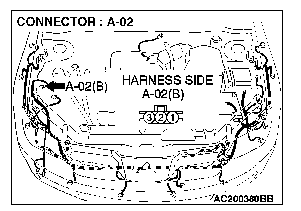
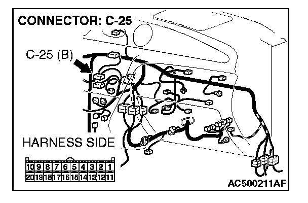
STEP 24. Check A/C pressure sensor connector A-02 and A/C-ECU connector C-25 for damage.
Q: Are A/C pressure sensor connector A-02 and A/C-ECU connector C-25 in good condition?
YES: Go to Step 25.
NO: Repair or replace the connector. Check that the air conditioning works normally.
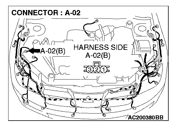
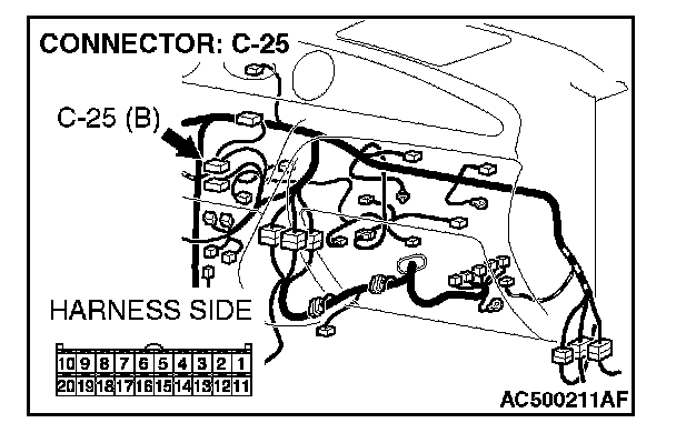
STEP 25. Check the wiring harness between A/C pressure sensor connector A-02 (terminal 2) and A/C-ECU connector C-25 (terminal 11).
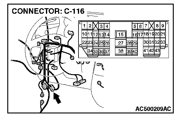
NOTE: Also check intermediate connector C-116. If intermediate connector C-116 is damaged, repair or replace the connector as described in Harness Connector Inspection.
Q: Are the wiring harness between A/C pressure sensor connector A-02 (terminal 2) and A/C-ECU connector C-25 (terminal 11) in good condition?
YES: Go to Step 26.
NO: Repair the wiring harness. Check that the air conditioning works normally.
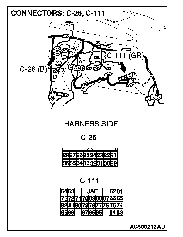
STEP 26. Check powertrain control module connector C-111 and A/C-ECU connector C-26 for damage.
Q: Are powertrain control module connectors C-111 and A/C-ECU connector C-26 in good condition?
YES: Go to Step 27.
NO: Repair or replace the connector. Check that the air conditioning works normally.
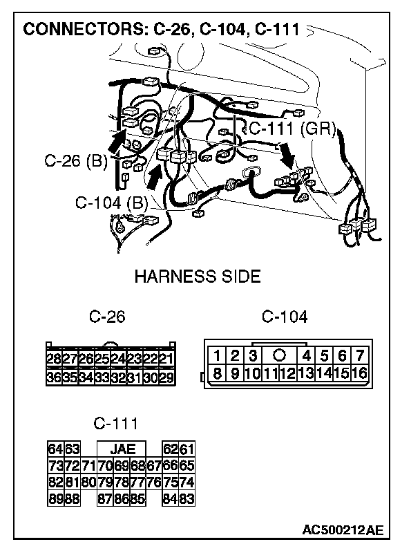
STEP 27. Check the wiring harness between powertrain control module connectors C-111 (terminals 69 and 78) and A/C-ECU connector C-26 (terminals 34 and 32).
NOTE: Also check intermediate connector C-104. If intermediate connector C-104 is damaged, repair or replace the connector as described in Harness Connector Inspection.
Q: Are the wiring harness between powertrain control module connectors C-111 (terminals 69 and 78) and A/C-ECU connector C-26 (terminals 34 and 32) in good condition?
YES: Replace the A/C-ECU, powertrain control module. Check that the air conditioning works normally
NO: Repair the wiring harness. Check that the air conditioning works normally.