Inspection Procedure 1
INSPECTION PROCEDURE 1: Communication with the Scan Tool MB991958 is not possible.Data Link Connector Circuit:
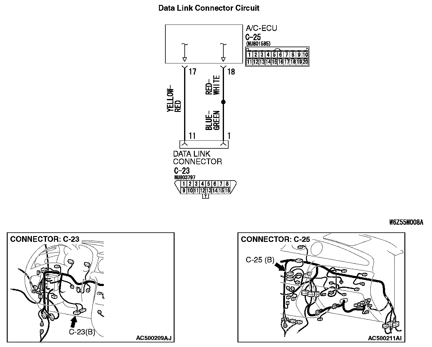
CIRCUIT OPERATION
If communication with all other systems is not possible, there is a high possibility that there is a malfunction of the diagnosis line. If only the A/C system can not communicate with the scan tool, the diagnosis line between the A/C-ECU and the data link connector may be defective.
TROUBLESHOOTING HINTS
- Damaged harness wires or connectors
- Malfunction of the A/C-ECU
DIAGNOSIS
Required Special Tools:
- MB991223: Harness Set
- MB992006: Extra Fine Probe
- MB991958: Scan Tool (MUT-III Sub Assembly)
- MB991824: Vehicle Communication Interface (V.C.I.)
- MB991827: MUT-III USB Cable
- MB991910: MUT-III Main Harness A (Vehicles with CAN communication system)
STEP 1. Check the communication with other systems.
Q: Is the communication with the other systems possible using the scan tool?
YES: Go to Step 2.
NO: Check the diagnosis line using the scan tool, and repair if necessary.
STEP 2. Check operations of the air conditioner, defogger and outside/inside air selection damper control motor.
Q: Does the air conditioner, defogger or outside/inside air selection damper control motor operate?
YES: Go to Step 3.
NO: Refer to Inspection procedure 10 "Malfunction of the A/C-ECU power supply system."
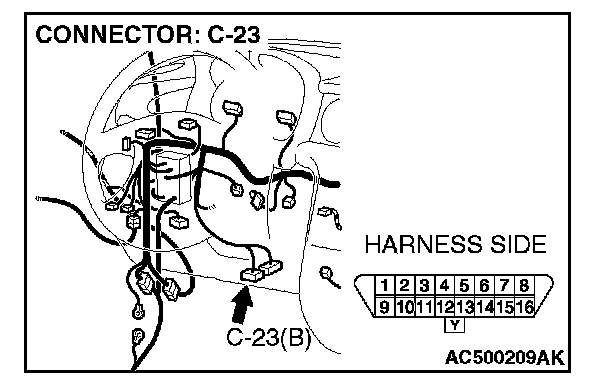
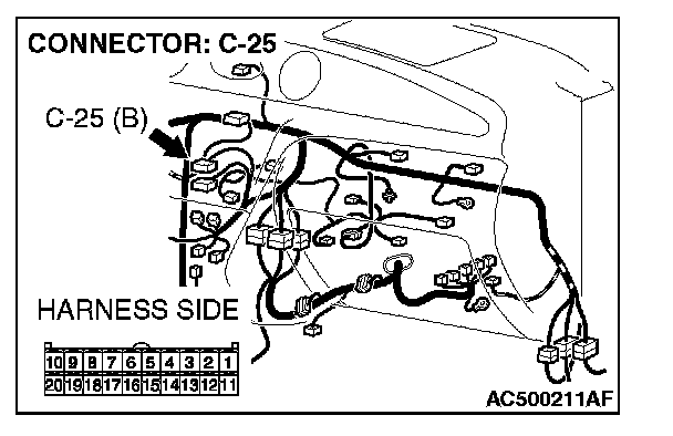
STEP 3. Check A/C-ECU connector C-25 and diagnosis connector C-23 for loose, corroded or damaged terminals, or terminals pushed back in the connector.
Q: Is the check result normal?
YES: Go to Step 4.
NO: Repair the connector.
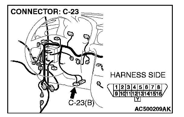

STEP 4. Check the wiring harness between A/C-ECU connector C-25 (terminal 17 and 18) and diagnosis connector C-23 (terminal 11 and 1).
- Check the communication lines for open or short circuit.
Q: Is the check result normal?
YES: Replace the A/C-ECU.
NO: Repair the wiring harness.