Camshaft: Service and Repair
Part 1 Of 3:
Part 2 Of 3:
Part 3 Of 3:

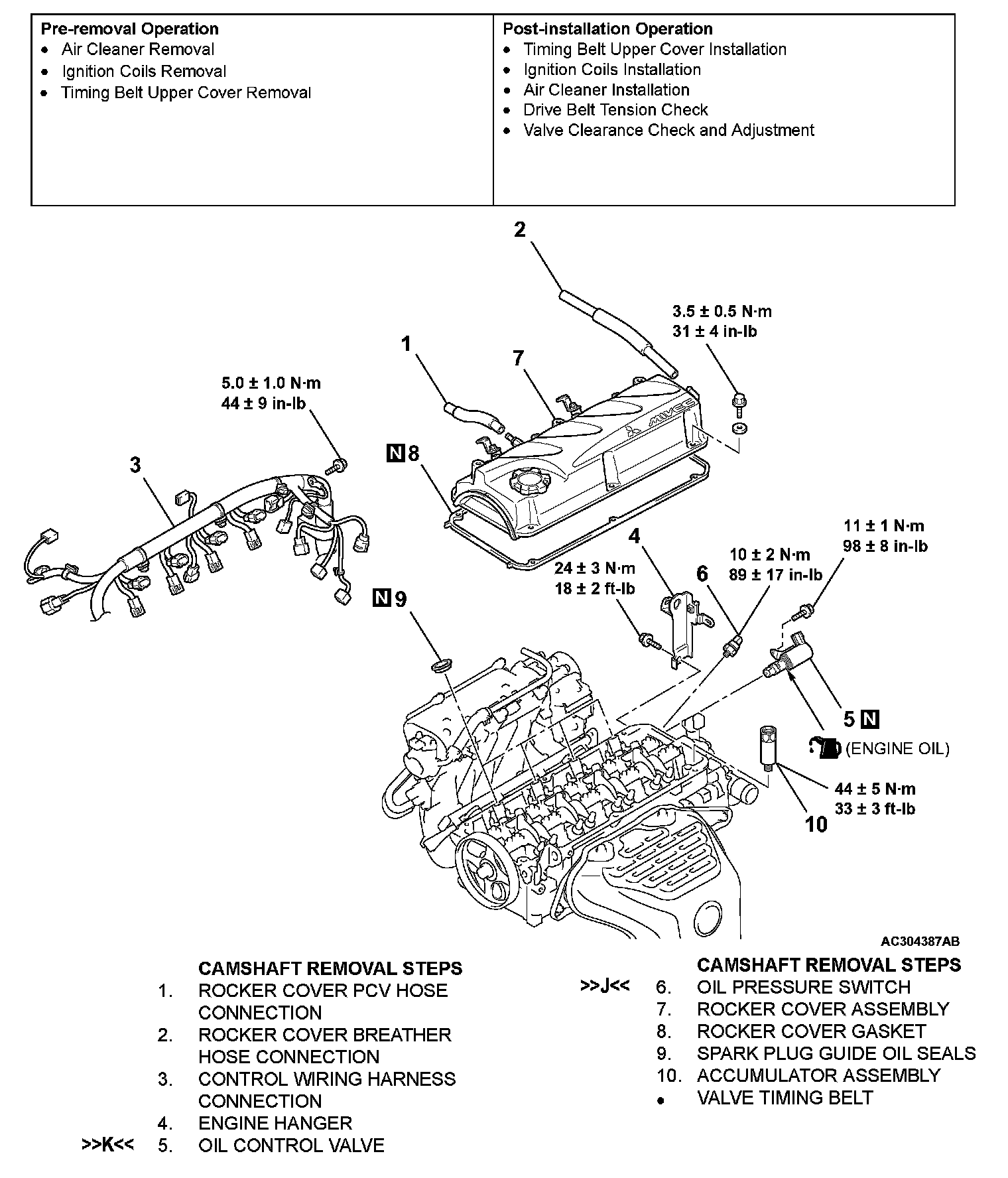
CAMSHAFT AND VALVE STEM SEAL
REMOVAL AND INSTALLATION
CAUTION:
^ Remove and assemble the marked parts in each cylinder unit.
REMOVAL SERVICE POINTS
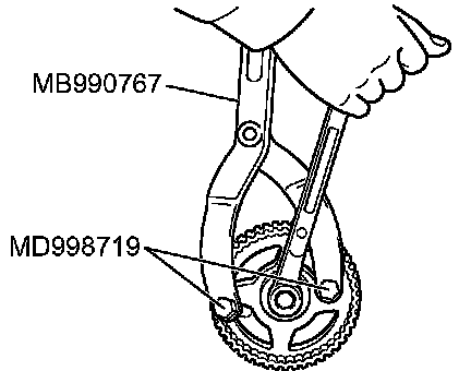
[[A]] CAMSHAFT SPROCKET REMOVAL
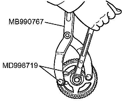
1. Hold the camshaft sprocket with special tools MB990767 and MD998719.
2. Loosen the camshaft sprocket mounting bolt and remove the camshaft sprocket.
[[B]] EXHAUST ROCKER ARM AND SHAFT ASSEMBLY/INLET ROCKER ARM AND SHAFT ASSEMBLY REMOVAL
CAUTION: Never disassemble the exhaust rocker arm and shaft assembly, and inlet rocker arm and shaft assembly.
[[C]] VALVE SPRING RETAINER LOCKS REMOVAL
CAUTION: When removing valve spring retainer locks, leave the piston of each cylinder in the Top Dead Center (TDC) position. The valve may fall into the cylinder if the piston is not properly in the TDC position.
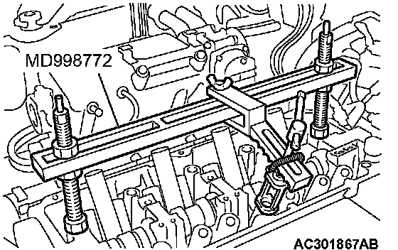
Use special tool MD998772 to compress the valve spring and then remove the valve spring retainer locks.
INSTALLATION SERVICE POINTS
]]A[[ VALVE STEM SEALS INSTALLATION
1. Apply a small amount of engine oil to the valve stem seals.
CAUTION:
^ Do not re-use the valve stem seal.
^ The special tool MD998774 must be used to install the valve stem seal. Improper installation could result in oil leaking past the valve guide.
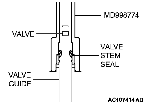
2. Use special tool MD998774 to fill a new valve stem seal in the valve guide using the valve stem area as a guide.
]]B[[ EXHAUST VALVE SPRINGS/INLET VALVE SPRINGS INSTALLATION
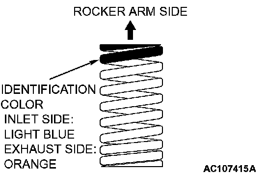
Install the valve springs with its identification color painted end facing the locker arm.
]]C[[ VALVE SPRING RETAINER LOCKS INSTALLATION
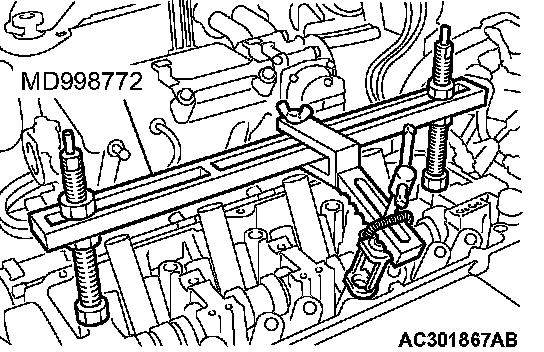
Use special tool MD998772 to compress the valve spring and then install the valve spring retainer lock in the same manner as removal.
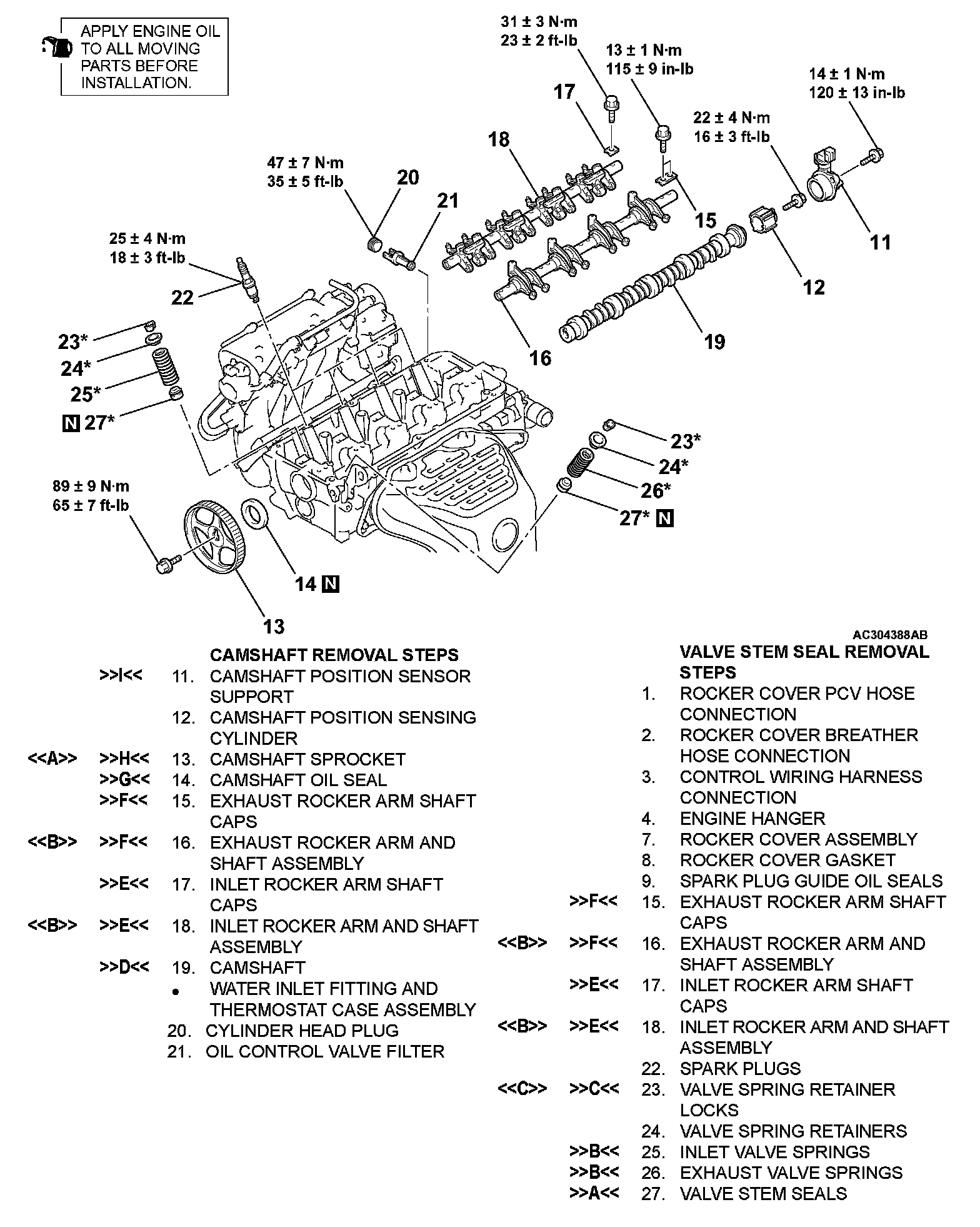
]]D[[ CAMSHAFT INSTALLATION
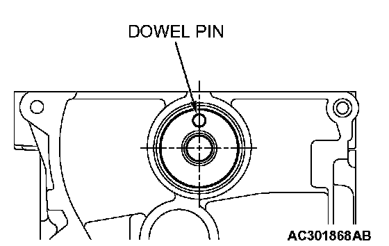
Set the dowel pin of the camshaft in the position shown in the figure.
]]E[[ INLET ROCKER ARM AND SHAFT ASSEMBLY/INLET ROCKER ARM SHAFT CAPS INSTALLATION
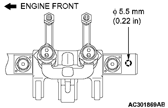
1. Place the inlet rocker shaft so that its 5.5 mm (0.22 inch) hole faces toward the cylinder head.
2. Install the inlet rocker arm shaft caps.
3. Tighten the inlet rocker shaft mounting bolts to the specified torque.
Tightening torque: 31 ± 3 Nm (23 ± 2 ft. lbs.)
]]F[[ EXHAUST ROCKER ARM AND SHAFT ASSEMBLY/EXHAUST ROCKER ARM SHAFT CAPS INSTALLATION
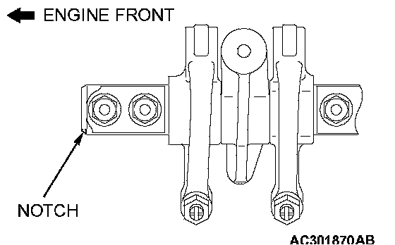
1. Install the exhaust rocker shaft so that its notch is positioned as shown.
2. Install the exhaust rocker arm shaft caps.
3. Tighten the exhaust rocker shaft mounting bolts to the specified torque.
Tightening torque: 13 ± 1 Nm (115 ± 9 inch lbs.)
]]G[[ CAMSHAFT OIL SEAL INSTALLATION
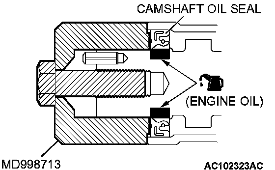
1. Apply engine oil to the entire inner diameter of the oil seal lip.
2. Use special tool MD998713 to press-fit the oil seal as shown.
]]H[[ CAMSHAFT SPROCKET INSTALLATION
1. Hold the camshaft sprocket with special tools MB990767 and MD998719 in the same manner as removal.
2. Tighten the camshaft sprocket mounting bolt to the specified torque.
Tightening torque: 89 ± 9 Nm (65 ± 7 ft. lbs.)
]]I[[ CAMSHAFT POSITION SENSOR SUPPORT INSTALLATION
1. Remove sealant from the camshaft position sensor support and cylinder head surfaces.
2. Apply the sealant to the camshaft position sensor support flange in a continuous bead as shown in the illustration.
Specified sealant: 3M(TM) AAD Part No.8672, 3M(TM) AAD Part No.8679/8678 or equivalent
NOTE: Install the camshaft position sensor support within 15 minutes after applying the sealant.
3. Install the camshaft position sensor support to the cylinder head.
CAUTION: Wait at least one hour. Never start the engine or let engine oil or coolant touch the adhesion surface during that time.
4. Tighten the camshaft position sensor support mounting bolts to the specified torque.
Tightening torque: 14 ± 1 Nm (120 ± 13 inch lbs.)
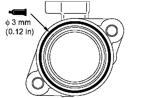
]]J[[ OIL PRESSURE SWITCH INSTALLATION
1. Remove sealant from the oil pressure switch and cylinder head surfaces.
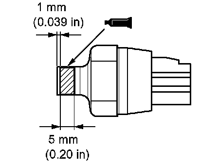
2. Apply sealant to the thread of the oil pressure switch as shown.
Specified sealant: 3M(TM) AAD Part No.8672, 3M(TM) AAD Part No.8679/8678 or equivalent
NOTE: Install the oil pressure switch within 15 minutes after applying the sealant.
CAUTION: Wait at least one hour. Never start the engine or let engine oil or coolant touch the adhesion surface during that time.
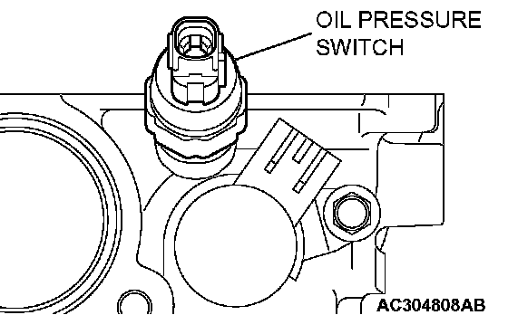
3. Tighten the oil pressure switch to the specified torque as shown.
Tightening torque: 10 ± 2 Nm (89 ± 17 inch lbs.)
]]K[[ OIL CONTROL VALVE INSTALLATION
1. Apply a little engine oil to the oil control valve O-ring.
2. Assemble the oil control valve to the cylinder head.
3. Tighten the oil control valve mounting bolt to the specified torque.
Tightening torque: 11 ± 1 Nm (98 ± 8 inch lbs.)