Inspection Procedure 2: When the Ignition Key Is Turned to on (Engine Stopped), the ABS Warning Light Does Not Illuminate
INSPECTION PROCEDURE 2: When the Ignition Key is Turned to ON (Engine Stopped), the ABS Warning Light does not Illuminate.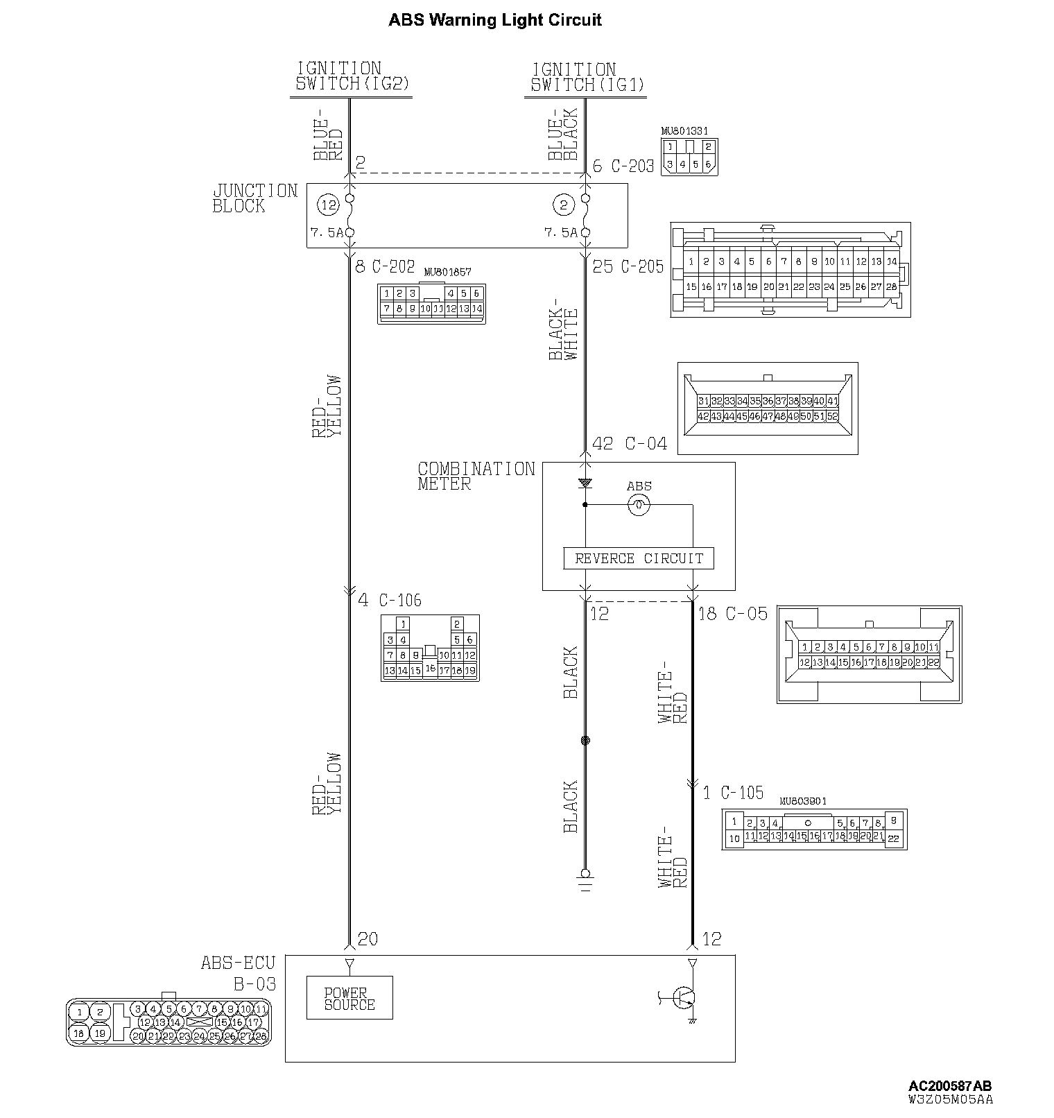
CIRCUIT OPERATION
^ The ABS warning light is lit up by transistor control in the ABS-ECU. However, the relationship of the reverse circuit movement in the combination meter will vary from usual in terms of transistor ON/OFF and ABS warning light ON/OFF, in that the ABS warning light will light up when the transistor is turned OFF for this circuit. This is how the ABS warning light lights up even when the ABS-ECU connector is connected improperly or if the ABS-ECU function has terminated.
^ The ABS-ECU also lights up the ABS warning light during the initial check (approximately 3 seconds) when the ignition switch is turned ON in addition to when the system is malfunctioning.
TECHNICAL DESCRIPTION (COMMENT)
Possible causes include the combination meter power circuit, disconnected ground circuit, dead light bulb, or short circuited ABS warning light.
TROUBLESHOOTING HINTS (THE MOST LIKELY CAUSES FOR THIS CASE:)
^ Blown fuse
^ Damaged wiring harness or connector
^ Burnt out ABS warning light bulb
^ Combination meter defect
^ Malfunction of the hydraulic unit (integrated with ABS-ECU)
DIAGNOSIS
Required Special Tool:
^ MB991223: Harness Set
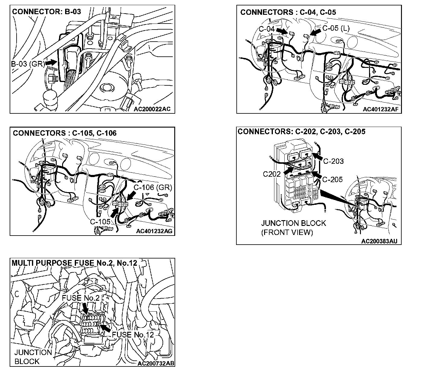
STEP 1. Check the ABS warning light circuit at ABS-ECU connector B-03.
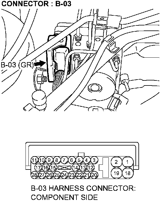
1. Disconnect ABS-ECU connector B-03.
2. Turn the ignition switch to the ON position.
Q: Does the ABS warning light illuminate?
YES: Retest the system. If the malfunction persists, replace the hydraulic unit (integrated with ABS-ECU). Then go to Step 7. If the malfunction is not reproduced, an intermittent malfunction is suspected.
NO: Go to Step 2.
STEP 2. Check the ABS warning light bulb.
1. Remove the combination meter.
2. Check the ABS warning light bulb.
Q: Is the bulb burned out?
YES: Replace the bulb and then go to Step 7.
NO: Go to Step 3.
STEP 3. Check the combination meter power supply circuit.
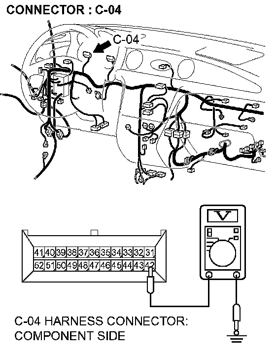
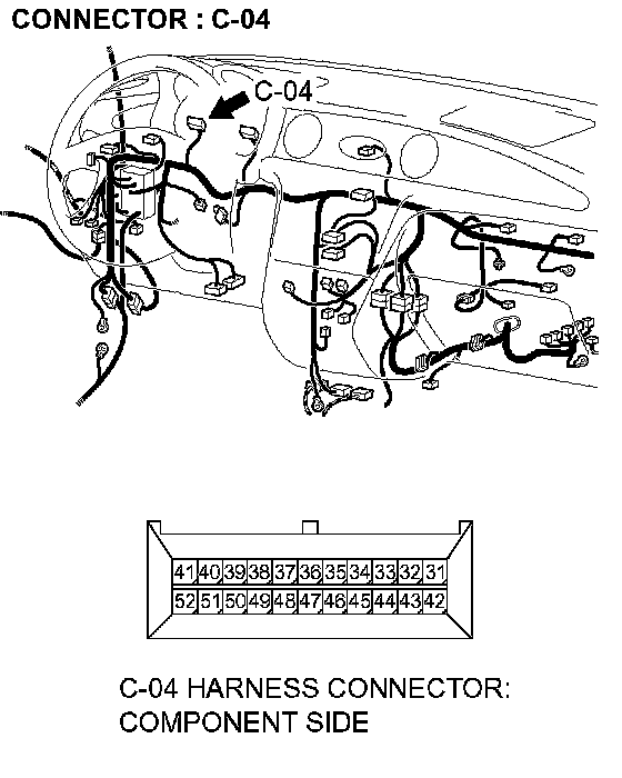
1. Disconnect connector C-04, and check at the harness side.
2. Turn the ignition switch to the ON position.
3. Measure the voltage between terminal 42 and ground. It should be battery positive voltage (approximately 12 volts) present.
Q: Is battery positive voltage (approximately 12 volts) present?
YES: Go to Step 4.
NO: Go to Step 6.
STEP 4. Check the harness wire between the combination meter connector C-05 terminal 12 and ground.
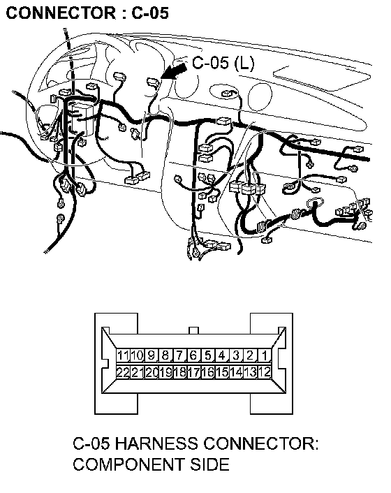
Q: Is the harness wire between combination meter connector C-05 terminal 12 and ground?
YES: Go to Step 5.
NO: Repair it and go to Step 7.
STEP 5. Check the harness wire between the combination meter connector C-05 terminal 18 and ABS-ECU connector B-03 terminal 12.
NOTE: After inspecting intermediate connector C- 105, inspect the wire. If the intermediate connector C-105 is damaged, repair or replace it.If the connector has been repaired or replaced, go to Step 7.
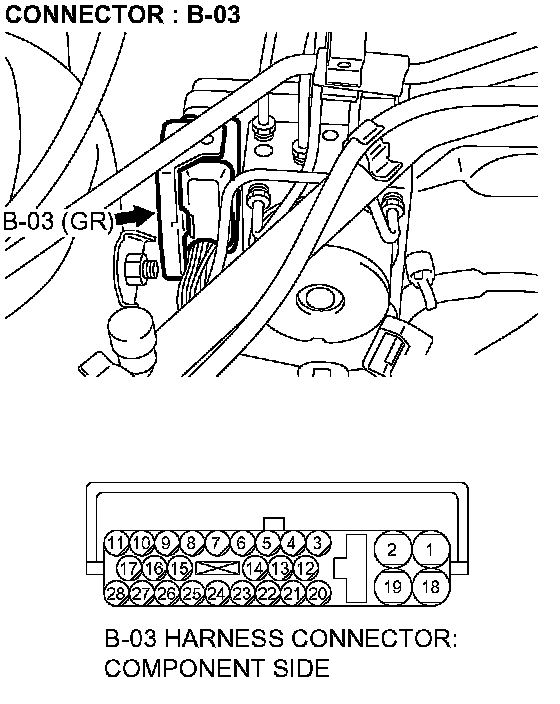
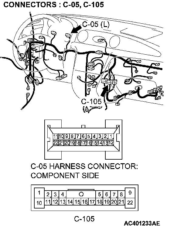
Q: Is the harness wire between the combination meter connector C-05 terminal 18 and ABS-ECU connector B-03 terminal 12 damaged?
YES: Replace the combination meter and go to Step 7.
NO: Repair it and go to Step 7.
STEP 6. Check the harness wire between the ignition switch (IG1) C-303 terminal 2 and the combination meter C-04 terminal 42.
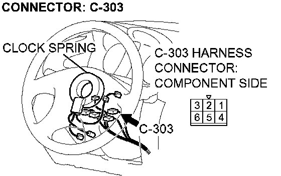
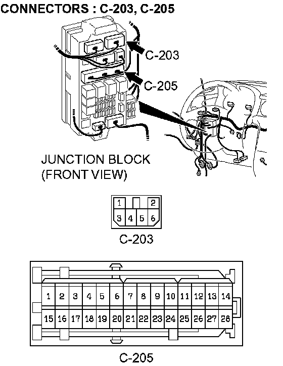
NOTE: After inspecting intermediate connectors C-203 and C-205, inspect the wire. If the intermediate connector C-203 or C-205 is damaged, repair or replace it. If the connector has been repaired or replaced, go to Step 7.
Q: Is the harness wire between the ignition switch (IG1) C-303 terminal 2 and combination meter connector C-04 terminal 42 ground?
YES: Repair it and go to Step 7.
NO: Go to Step 7.
STEP 7. Retest the system.
Q: Does the ABS warning light illuminate for 3 seconds when the ignition switch is turned to the ON position with engine stopped or upon start-up?
YES: The procedure is complete.
NO: Return to Step 1.