Part - 2
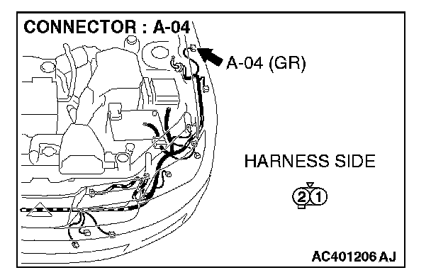

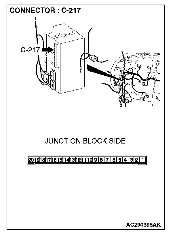
STEP 26. Check the wiring harness between side turn-signal light (LH) connector A-04 (terminal 2) and ETACS-ECU connector C-217 (terminal 14).
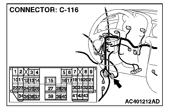
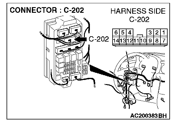
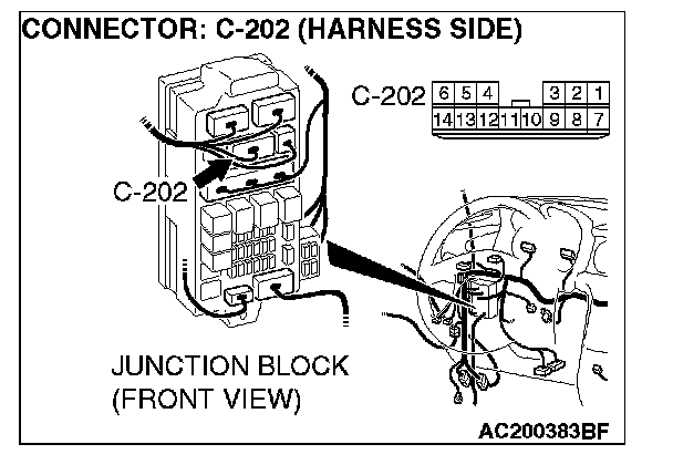
NOTE: Also check junction block connector C-202 and intermediate connector C-116 for loose, corroded, or damaged terminals, or terminals pushed back in the connector. If junction block connector C-202 or intermediate connector C-116 is damaged, repair or replace the damaged component(s) as described in Harness Connector Inspection.
Q: Is the wiring harness between side turn-signal light (LH) connector A-04 (terminal 2) and ETACS-ECU connector C-217 (terminal 14) in good condition?
YES: Replace the socket. Verify that the turn-signal lights illuminate normally.
NO: The wiring harness may be damaged or the connector(s) may have loose, corroded or damaged terminals, or terminals pushed back in the connector. Repair the wiring harness as necessary. Verify that the turn-signal lights illuminate normally.
STEP 27. Check the side turn-signal light bulb (RH).
1. Remove the side turn-signal light (RH) bulb.
2. Verify that the side turn-signal light bulb (RH) is not damaged or burned out.
Q: Is the side turn-signal light (RH) bulb in good condition?
YES: Go to Step 28.
NO: Replace the side turn-signal light (RH) bulb. Verify that the turn-signal lights illuminate normally.
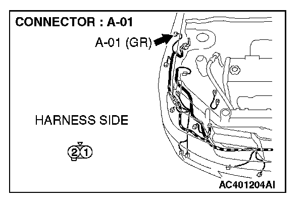
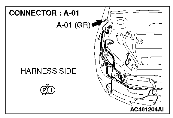
STEP 28. Check side turn-signal light (RH) connector A-01 for loose, corroded or damaged terminals, or terminals pushed back in the connector.
Q: Is the side turn-signal light (RH) connector A-01 in good condition?
YES: Go to Step 29.
NO: Repair or replace the damaged component(s). Verify that the turn-signal lights illuminate normally.
STEP 29. Check the ground circuit to the side turn-signal light (RH). Measure the resistance at side turn-signal light (RH) connector A-01.
1. Disconnect side turn-signal light (RH) connector A-01 and measure the resistance available at the wiring harness side of the connector.
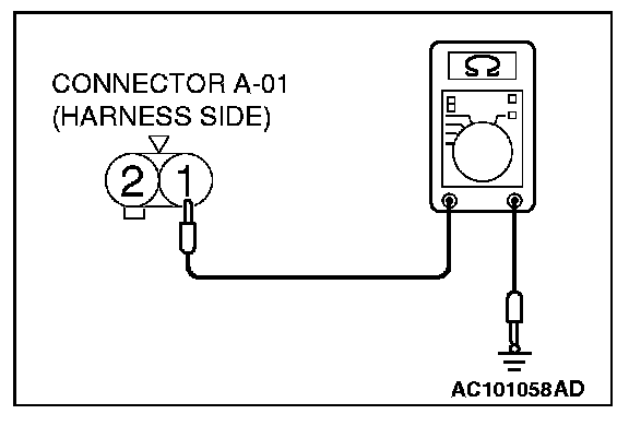
2. Measure the resistance value between terminal 1 and ground.
The resistance should equal 2 ohms or less.
Q: Is the measured resistance 2 ohms or less?
YES: Go to Step 31.
NO: Go to Step 30.
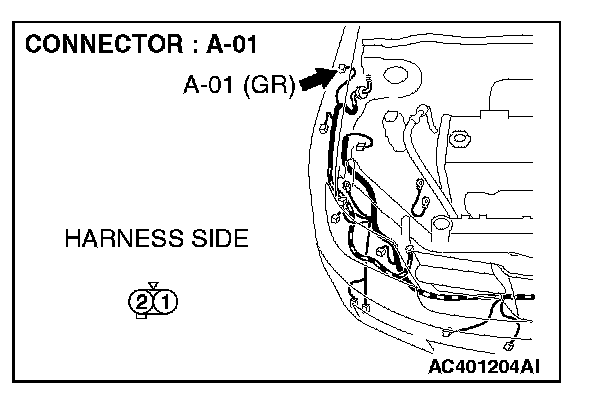
STEP 30. Check the wiring harness between side turn-signal light (RH) connector A-01 (terminal 1) and ground.
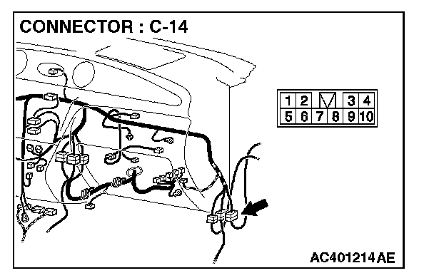
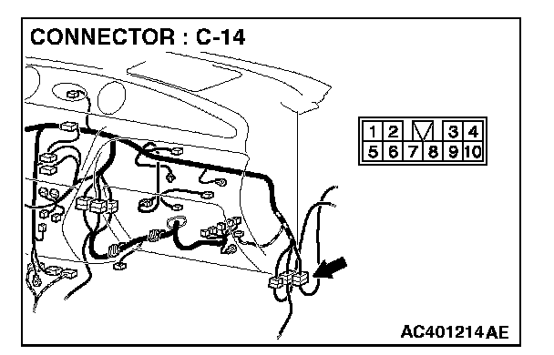
NOTE: Also check intermediate connector C-14 for loose, corroded, or damaged terminals, or terminals pushed back in the connector. If intermediate connector C-14 is damaged, repair or replace the damaged component(s) as described in Harness Connector Inspection.
Q: Is the wiring harness between side turn-signal light (RH) connector A-01 (terminal 1) and ground in good condition?
YES: Replace the socket. Verify that the turn-signal lights illuminate normally.
NO: The wiring harness may be damaged or the connector(s) may have loose, corroded or damaged terminals, or terminals pushed back in the connector. Repair the wiring harness as necessary. Verify that the turn-signal lights illuminate normally.
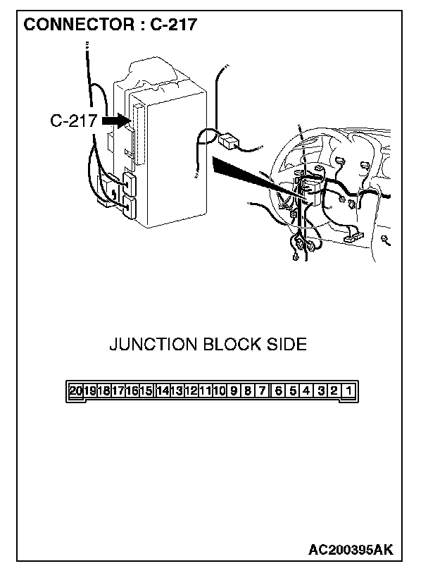
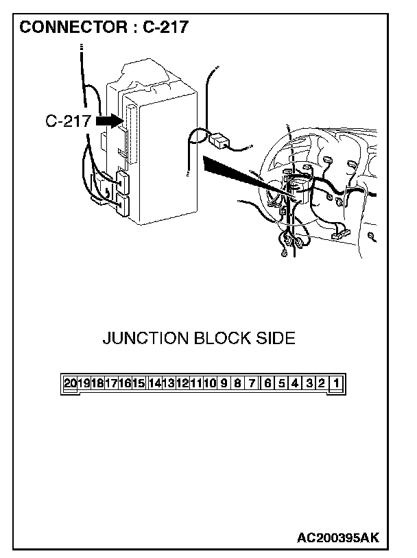
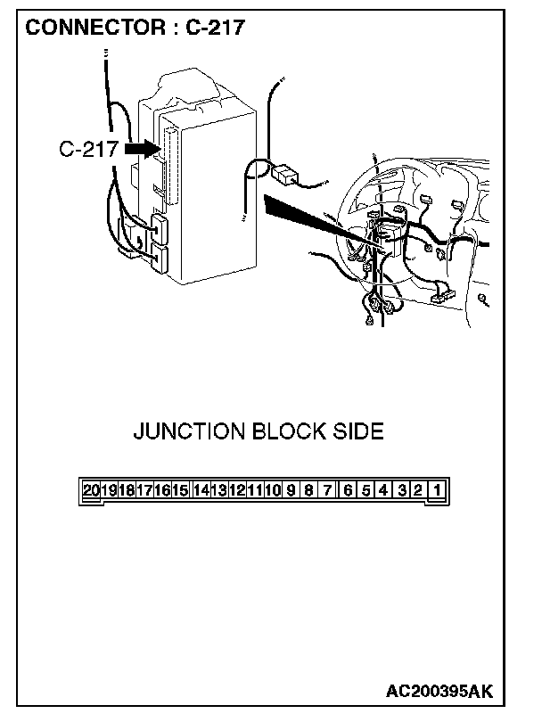
STEP 31. Check ETACS-ECU connector C-217 for loose, corroded or damaged terminals, or terminals pushed back in the connector.
Q: Is ETACS-ECU connector C-217 in good condition?
YES: Go to Step 32.
NO: Repair or replace the damaged component(s). Verify that the turn-signal lights illuminate normally.
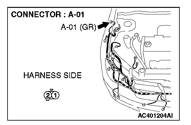

STEP 32. Check the wiring harness between side turn-signal light (RH) connector A-01 (terminal 2) and ETACS-ECU connector C-217 (terminal 9).
NOTE: Also check junction block connector C-202 and intermediate connector C-14 for loose, corroded, or damaged terminals, or terminals pushed back in the connector. If junction block connector C-202 or intermediate connector C-14 is damaged, repair or replace the damaged component(s) as described in Harness Connector Inspection.
Q: Is the wiring harness between side turn-signal light (RH) connector A-01 (terminal 2) and ETACS-ECU connector C-217 (terminal 9) in good condition?
YES: Replace the socket. Verify that the turn-signal lights illuminate normally.
NO: The wiring harness may be damaged or the connector(s) may have loose, corroded or damaged terminals, or terminals pushed back in the connector. Repair the wiring harness as necessary. Verify that the turn-signal lights illuminate normally.
STEP 33. Check the rear turn-signal light bulb (LH).
1. Remove the rear turn-signal (LH) light bulb.
2. Verify that the rear turn-signal light bulb (LH) is not damaged or burned out.
Q: Is the rear turn-signal (LH) light bulb in good condition?
YES: Go to Step 34.
NO: Replace the rear turn-signal (LH) light bulb. Verify that the turn-signal lights illuminate normally.
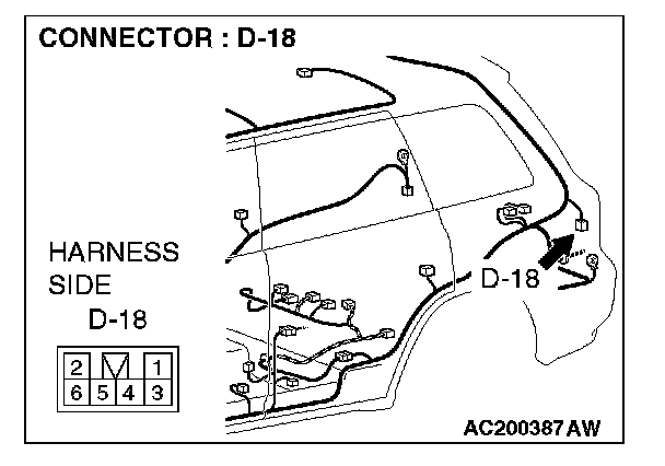
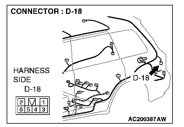
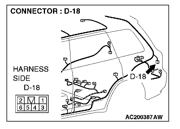
STEP 34. Check rear combination light (LH) connector D-18 for loose, corroded or damaged terminals, or terminals pushed back in the connector.
Q: Is rear combination light (LH) connector D-18 in good condition?
YES: Go to Step 35.
NO: Repair or replace the damaged component(s). Verify that the turn-signal lights illuminate normally.
STEP 35. Check the ground circuit to the rear combination light (LH). Measure the resistance at rear combination light (LH) connector D-18.
1. Disconnect rear combination light (LH) connector D-18 and measure the resistance available at the wiring harness side of the connector.
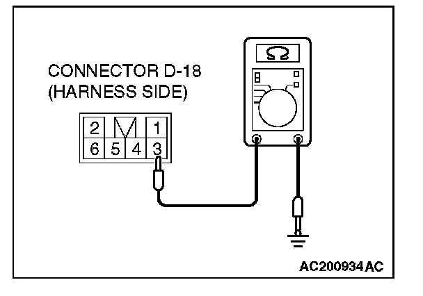
2. Measure the resistance value between terminal 3 and ground.
The resistance should equal 2 ohms or less.
Q: Is the measured resistance 2 ohms or less?
YES: Go to Step 37.
NO: Go to Step 36.
STEP 36. Check the wiring harness between rear combination light (LH) connector D-18 (terminal 3) and ground.
Q: Is the wiring harness between rear combination light (LH) connector D-18 (terminal 3) and ground in good condition?
YES: Replace the socket assembly. Verify that the turn-signal lights illuminate normally.
NO: The wiring harness may be damaged or the connector(s) may have loose, corroded or damaged terminals, or terminals pushed back in the connector. Repair the wiring harness as necessary. Verify that the turn-signal lights illuminate normally.
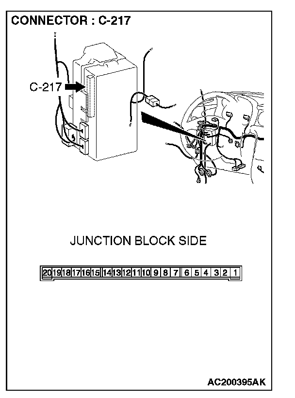
STEP 37. Check ETACS-ECU connector C-217 for loose, corroded or damaged terminals, or terminals pushed back in the connector.
Q: Is ETACS-ECU connector C-217 in good condition?
YES: Go to Step 38.
NO: Repair or replace the damaged component(s). Verify that the turn-signal lights illuminate normally.
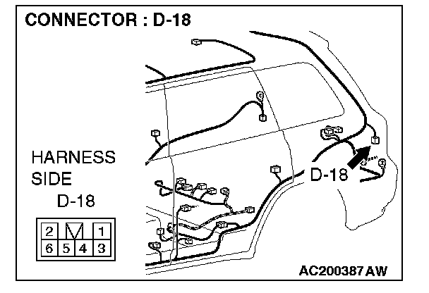
STEP 38. Check the wiring harness between rear combination light (LH) connector D-18 (terminal 6) and ETACS-ECU connector C-217 (terminal 14).
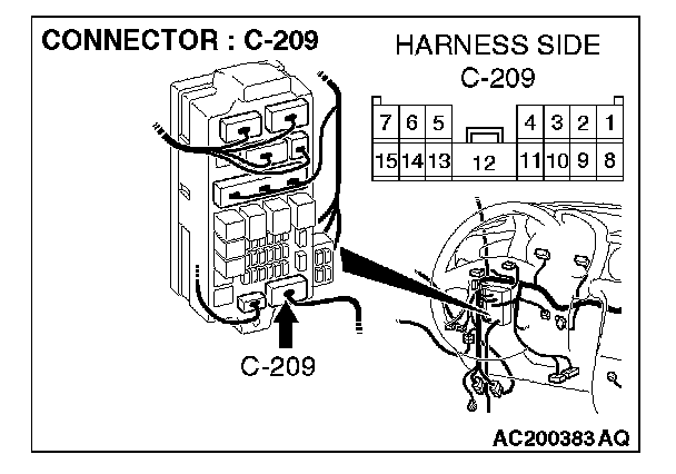
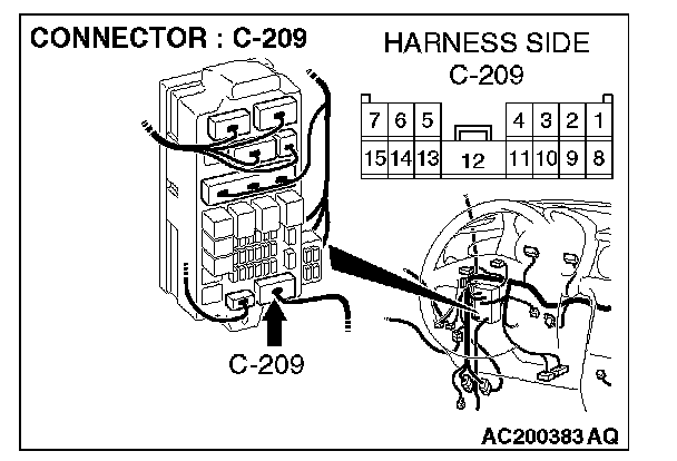
NOTE: Also check junction block connector C-209 for loose, corroded, or damaged terminals, or terminals pushed back in the connector. If junction block connector C-209 is damaged, repair or replace the damaged component(s) as described in Harness Connector Inspection.
Q: Is the wiring harness between rear combination light (LH) connector D-18 (terminal 6) and ETACS-ECU connector C-217 (terminal 14) in good condition?
YES: Replace the socket assembly. Verify that the turn-signal lights illuminate normally.
NO: The wiring harness may be damaged or the connector(s) may have loose, corroded or damaged terminals, or terminals pushed back in the connector. Repair the wiring harness as necessary. Verify that the turn-signal lights illuminate normally.
STEP 39. Check the rear turn-signal light bulb (RH).
1. Remove the rear turn-signal (RH) light bulb.
2. Verify that the rear turn-signal light bulb (RH) is not damaged or burned out.
Q: Is the rear turn-signal (RH) light bulb in good condition?
YES: Go to Step 40.
NO: Replace the rear turn-signal (RH) light bulb. Verify that the turn-signal lights illuminate normally.

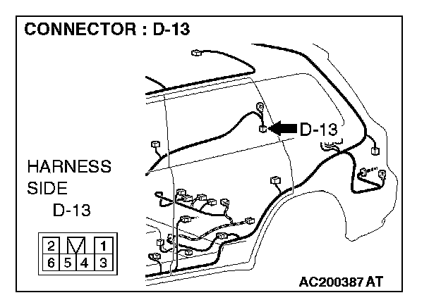
STEP 40. Check rear combination light (RH) connector D-13 for loose, corroded or damaged terminals, or terminals pushed back in the connector.
Q: Is rear combination light (RH) connector D-13 in good condition?
YES: Go to Step 41.
NO: Repair or replace the damaged component(s). Verify that the turn-signal lights illuminate normally.
STEP 41. Check the ground circuit to the rear combination light (RH). Measure the resistance at rear combination light (RH) connector D-13.
1. Disconnect rear combination light (RH) connector D-13 and measure the resistance available at the wiring harness side of the connector.
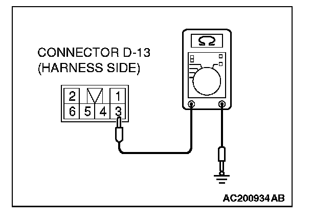
2. Measure the resistance value between terminal 3 and ground.
The resistance should equal 2 ohms or less.
Q: Is the measured resistance 2 ohms or less?
YES: Go to Step 43.
NO: Go to Step 42.
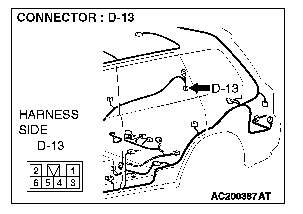
STEP 42. Check the wiring harness between rear combination light (RH) connector D-13 (terminal 3) and ground.
Q: Is the wiring harness between rear combination light (RH) connector D-13 (terminal 3) and ground in good condition?
YES: Replace the socket assembly. Verify that the turn-signal lights illuminate normally.
NO: The wiring harness may be damaged or the connector(s) may have loose, corroded or damaged terminals, or terminals pushed back in the connector. Repair the wiring harness as necessary. Verify that the turn-signal lights illuminate normally.
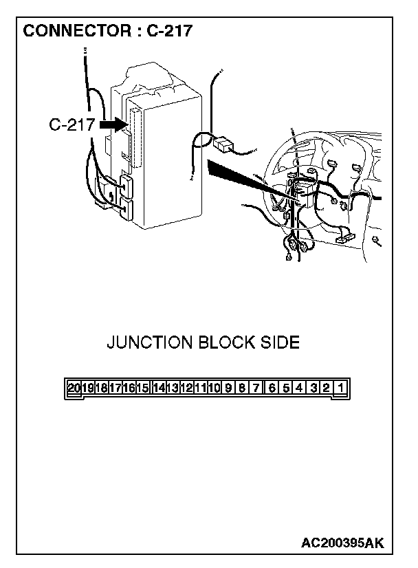
STEP 43. Check ETACS-ECU connector C-217 for loose, corroded or damaged terminals, or terminals pushed back in the connector.
Q: Is ETACS-ECU connector C-217 in good condition?
YES: Go to Step 44.
NO: Repair or replace the damaged component(s). Verify that the turn-signal lights illuminate normally.
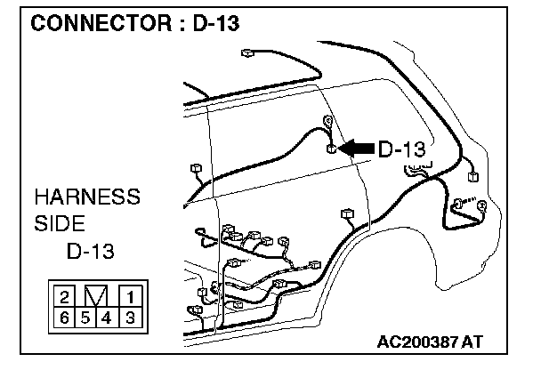
STEP 44. Check the wiring harness between rear combination light (RH) connector D-13 (terminal 6) and ETACS-ECU connector C-217 (terminal 9).
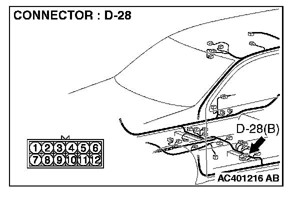
NOTE: Also check junction block connector C-209 and intermediate connector D-28 for loose, corroded, or damaged terminals, or terminals pushed back in the connector. If junction block connector C-209 or intermediate connector D-28 is damaged, repair or replace the damaged component(s) as described in Harness Connector Inspection.
Q: Is the wiring harness between rear combination light (RH) connector D-13 (terminal 6) and ETACS-ECU connector C-217 (terminal 9) in good condition?
YES: Replace the socket assembly. Verify that the turn-signal lights illuminate normally.
NO: The wiring harness may be damaged or the connector(s) may have loose, corroded or damaged terminals, or terminals pushed back in the connector. Repair the wiring harness as necessary. Verify that the turn-signal lights illuminate normally.
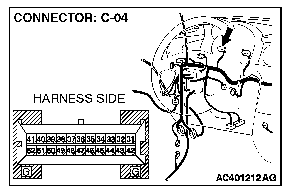

STEP 45. Check combination meter connector C-04 and ETACS-ECU connector C-217 for loose, corroded or damaged terminals, or terminals pushed back in the connector.
Q: Are combination meter connector C-04 and ETACS-ECU connector C-217 in good condition?
YES: Go to Step 46.
NO: Repair or replace the damaged component(s). Verify that the turn-signal lights illuminate normally.
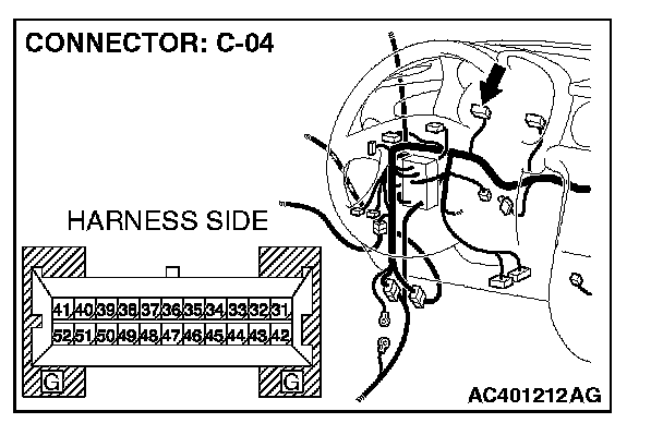
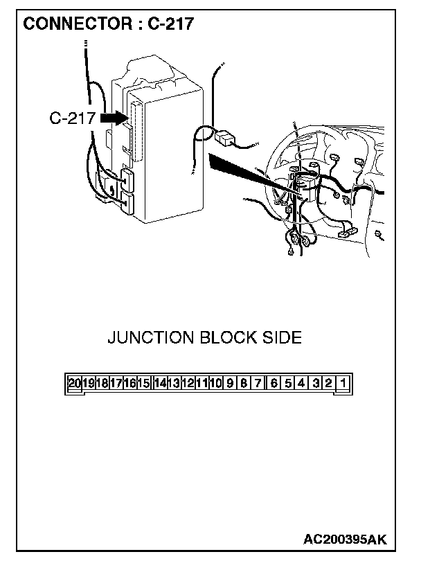
STEP 46. Check the wiring harness between combination meter connector C-04 (terminal 31) and ETACS-ECU connector C-217 (terminal 14).
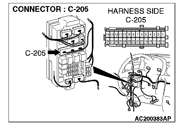
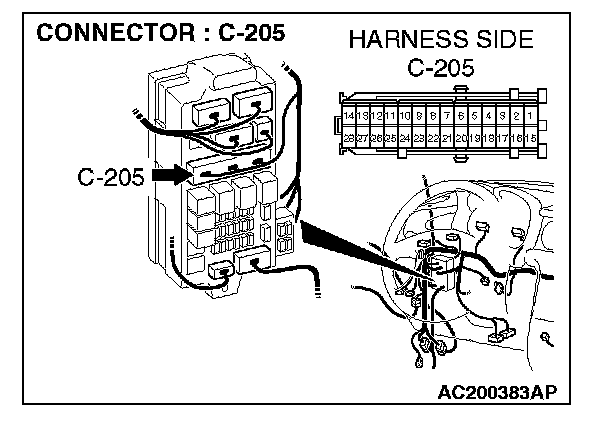
NOTE: Also check junction block connector C-205 for loose, corroded, or damaged terminals, or terminals pushed back in the connector. If junction block connector C-205 is damaged, repair or replace the damaged component(s) as described in Harness Connector Inspection.
Q: Is the wiring harness between combination meter connector C-04 (terminal 31) and ETACS-ECU connector C-217 (terminal 14) in good condition?
YES: Replace the combination meter. Verify that the turn-signal lights illuminate normally.
NO: The wiring harness may be damaged or the connector(s) may have loose, corroded or damaged terminals, or terminals pushed back in the connector. Repair the wiring harness as necessary. Verify that the turn-signal lights illuminate normally.
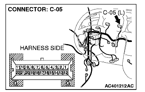
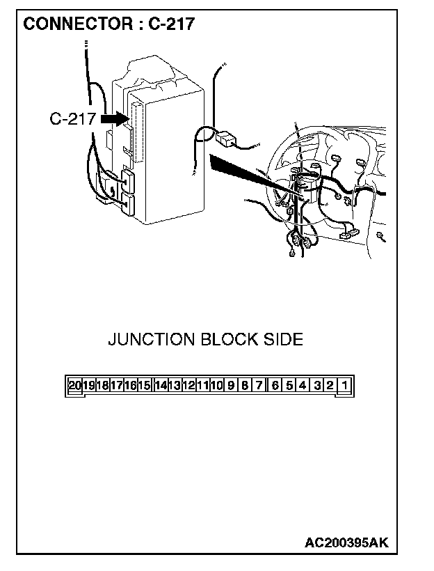
STEP 47. Check combination meter connector C-05 and ETACS-ECU connector C-217 for loose, corroded or damaged terminals, or terminals pushed back in the connector.
Q: Are combination meter connector C-05 and ETACS-ECU connector C-217 in good condition?
YES: Go to Step 48.
NO: Repair or replace the damaged component(s). Verify that the turn-signal lights illuminate normally.

STEP 48. Check the wiring harness between combination meter connector C-05 (terminal 10) and ETACS-ECU connector C-217 (terminal 9).
NOTE: Also check junction block connector C-205 for loose, corroded, or damaged terminals, or terminals pushed back in the connector. If junction block connector C-205 is damaged, repair or replace the damaged component(s) as described in Harness Connector Inspection.
Q: Is the wiring harness between combination meter connector C-05 (terminal 10) and ETACS-ECU connector C-217 (terminal 9) in good condition?
YES: Replace the combination meter. Verify that the turn-signal lights illuminate normally.
NO: The wiring harness may be damaged or the connector(s) may have loose, corroded or damaged terminals, or terminals pushed back in the connector. Repair the wiring harness as necessary. Verify that the turn-signal lights illuminate normally.
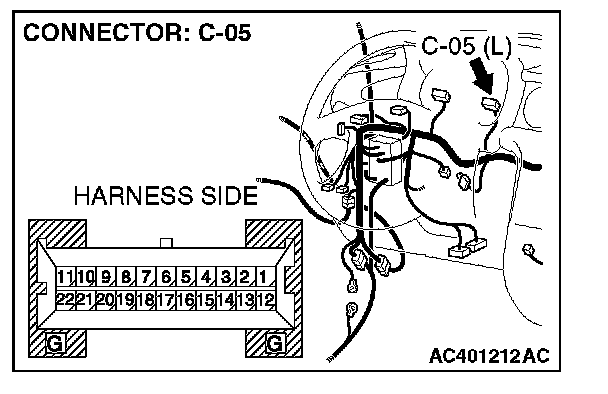
STEP 49. Check combination meter connector C-05 for loose, corroded or damaged terminals, or terminals pushed back in the connector.
Q: Is combination meter connector C-05 in good condition?
YES: Go to Step 50.
NO: Repair or replace the damaged component(s). Verify that the turn-signal lights illuminate normally.
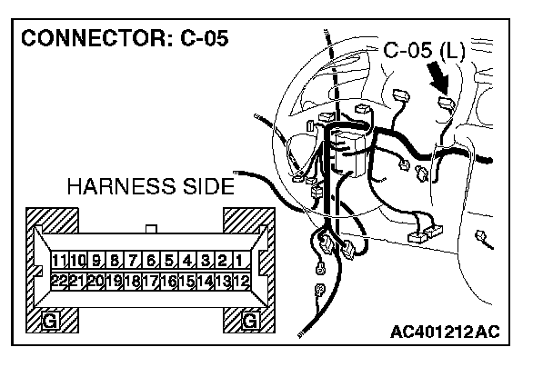
STEP 50. Check the wiring harness between combination meter connector C-05 (terminal 12) and ground.
Q: Is the wiring harness between combination meter connector C-05 (terminal 12) and ground in good condition?
YES: Replace the combination meter. Verify that the turn-signal lights illuminate normally.
NO: The wiring harness may be damaged or the connector(s) may have loose, corroded or damaged terminals, or terminals pushed back in the connector. Repair the wiring harness as necessary. Verify that the turn-signal lights illuminate normally.