Inspection Procedure 2
INSPECTION PROCEDURE 2: No Sound.Amplifier Power Supply Circuit:
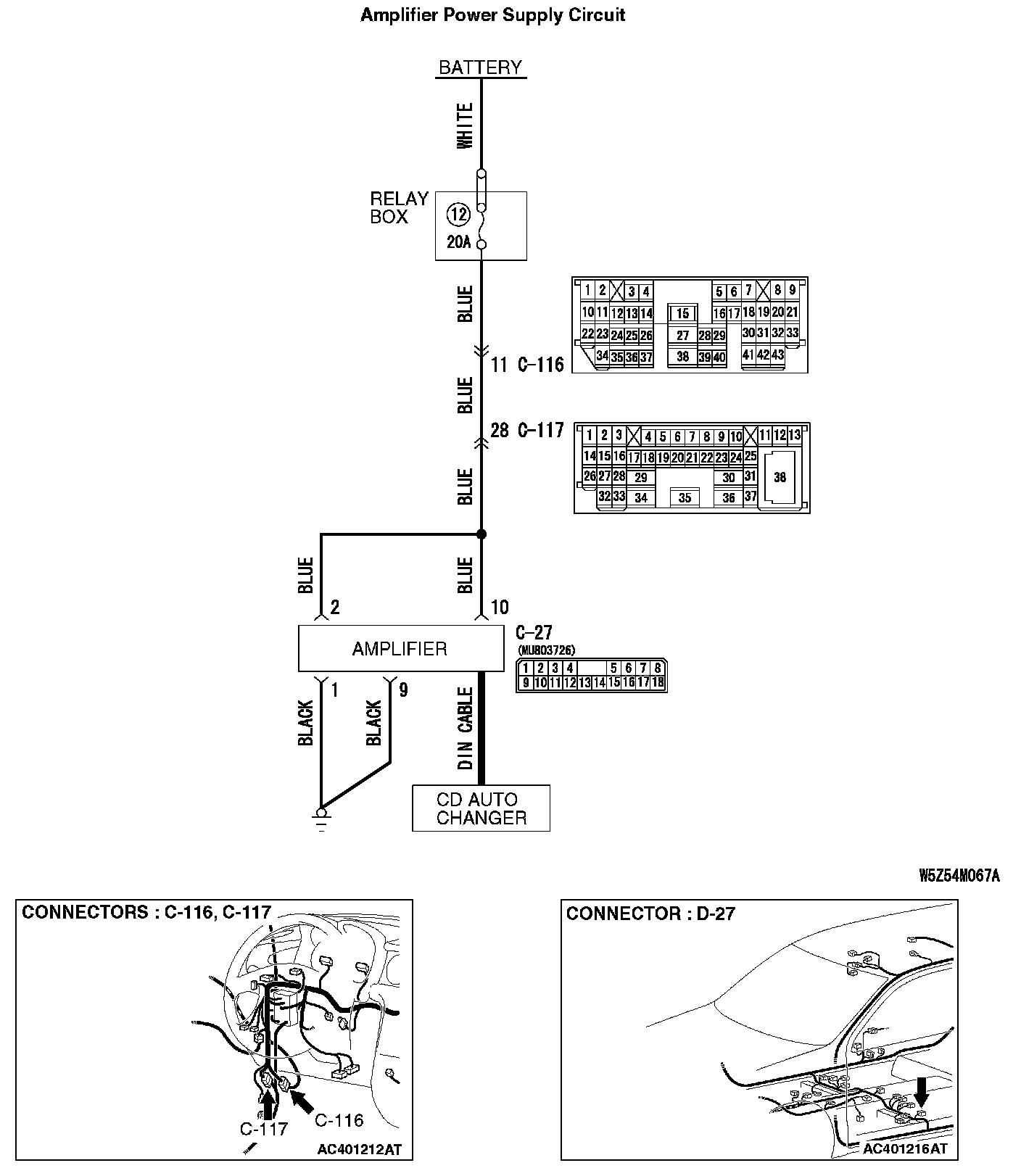
CIRCUIT OPERATION
Power is supplied to the amplifier when the battery.
TECHNICAL DESCRIPTION (COMMENT)
The cause is probably a faulty amplifier power supply circuit system.
TROUBLESHOOTING HINTS
- Damaged wiring harness or connector.
- Damaged DIN cable.
- Malfunction of the amplifier.
- Malfunction of the radio and CD player.
DIAGNOSIS
Required Special Tool:
- MB991223: Harness set
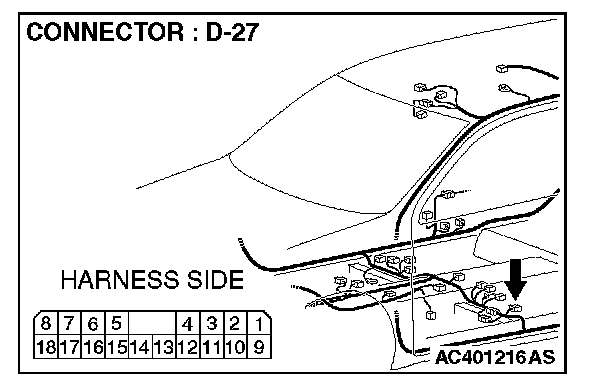
STEP 1. Measure at amplifier connector D-27 by backprobing in order to check the battery circuit of power supply system to the amplifier.
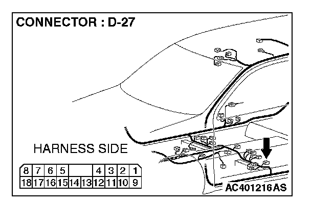
1. Measure at amplifier connector D-27 without disconnecting the connector.
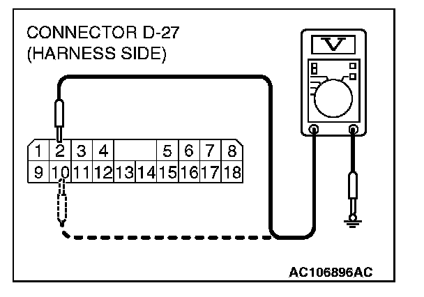
2. Measure the voltage between terminal 2 and ground.
The measured value should be approximately 12 volts (battery positive voltage).
3. Measure the voltage between terminal 10 and ground.
The measured value should be approximately 12 volts(battery positive voltage).
Q: Does the measured voltage correspond with this range?
YES: Go to Step 4.
NO: Go to Step 2.
STEP 2. Check amplifier connector D-27 for damage.
Q: Is amplifier connector D-27 in good condition?
YES: Go to Step 3.
NO: Repair or replace the connector. The speakers should sound.
STEP 3. Check the wiring harness between amplifier connector D-27 (terminal 10 and 2)and battery.
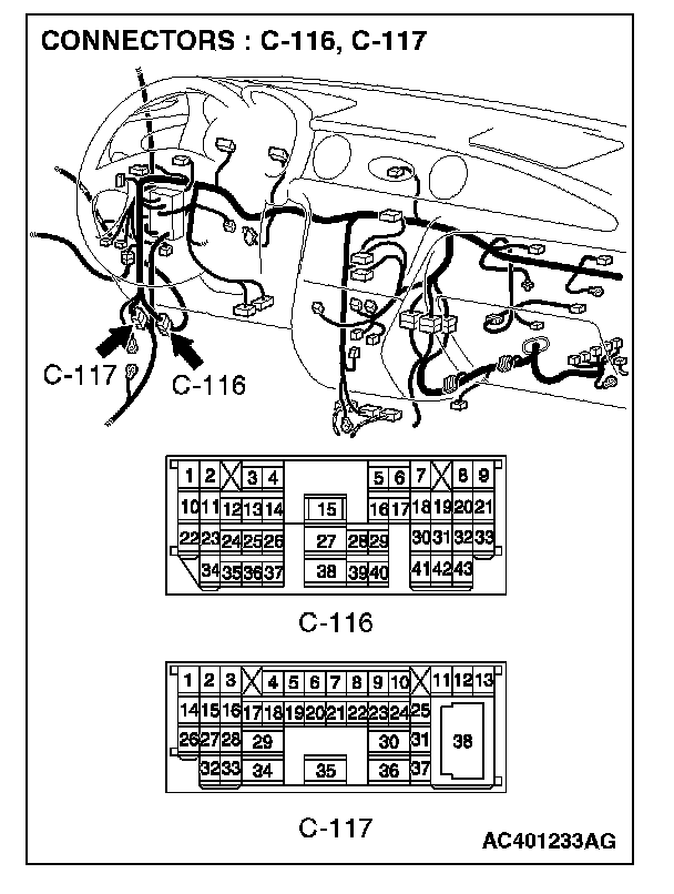
NOTE: Also check intermediate connector C-116 and C-117. If intermediate connectors C-116 or C-117 are damaged, repair or replace the connector as described in Harness Connector Inspection.
Q: Are the wiring harness between amplifier connector D-27 (terminal 10 and 2) and battery in good condition?
YES: There is no action to be taken.
NO: Repair the wiring harness. The speakers should sound.
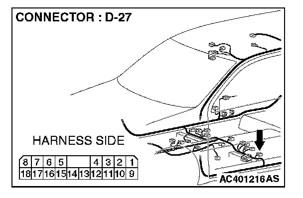
STEP 4. Measure at amplifier connector D-27 by backprobing in order to check the ground circuit to the amplifier.
1. Measure at amplifier connector D-27 without disconnecting the connector.
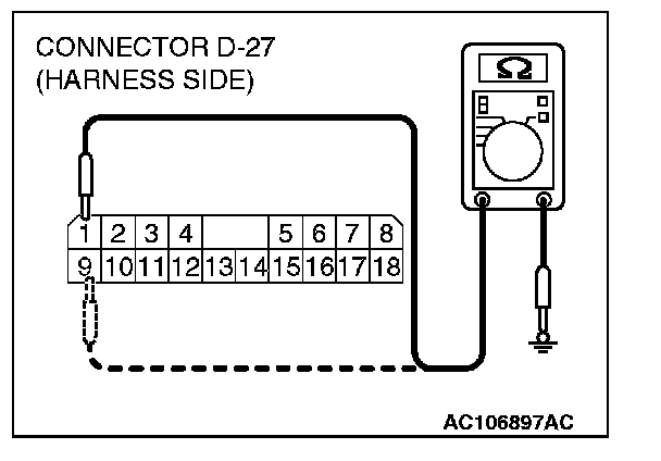
2. Measure the resistance between terminal 1 and ground by backprobing.
The measured value should be 2 ohms or less.
3. Measure the resistance between terminal 9 and ground by backprobing.
The measured value should be 2 ohms or less.
Q: Does the measured resistance value correspond with this range?
YES: Go to Step 7.
NO: Go to Step 5.
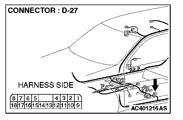
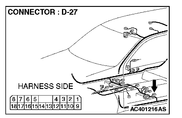
STEP 5. Check amplifier connector D-27 for damage.
Q: Is amplifier connector D-27 in good condition?
YES: Go to Step 6.
NO: Repair or replace the connector. The speakers should sound.
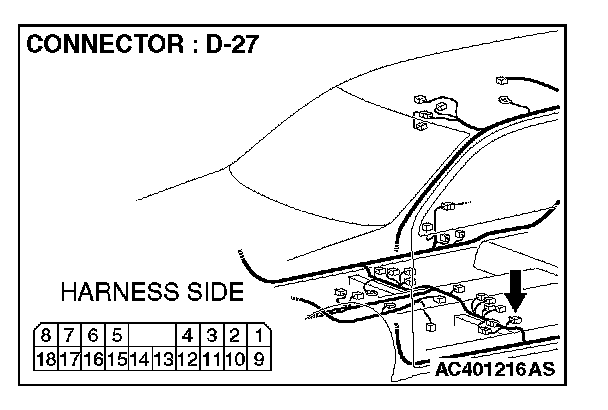
STEP 6. Check the wiring harness between amplifier connector D-27 (terminal 1 and 9) and ground.
Q: Are the wiring harness between amplifier connector D-27 (terminal 1 and 9) and ground in good condition?
YES: There is no action to be taken.
NO: Repair the wiring harness. The speakers should sound.
STEP 7. Check the DIN cable between amplifier and radio and CD player.
Q: Are the DIN cable in good condition?
YES: Go to Step 8.
NO: Repair or replace the DIN cable. The speakers should sound.
STEP 8. Replace the radio and CD player.
Q: Is sound output normally from all the speakers?
YES: There is no action to be taken.
NO: Repair or replace the amplifier. The speakers should sound.