Inspection Procedure 19
INSPECTION PROCEDURE 19: Preset Station are Erased.Memory Backup Power Circuit:
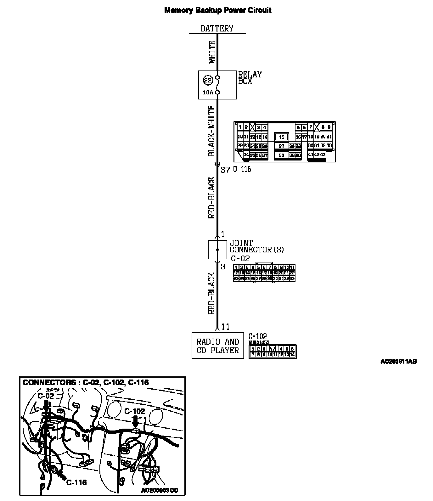
CIRCUIT OPERATION
The power is constantly supplied to the radio and CD player.
TECHNICAL DESCRIPTION (COMMENT)
The cause is probably a faulty radio and CD player memory backup power supply circuit system.
TROUBLESHOOTING HINTS
- Damaged wiring harness or connector.
- Malfunction of the radio and CD player.
DIAGNOSIS
Required Special Tool:
- MB991223: Harness set
STEP 1. Check at radio and CD player connector C-102 by backprobing in order to check the power supply circuit to the radio and CD player (through the battery).
1. Do not disconnect radio and CD player connector C-102.
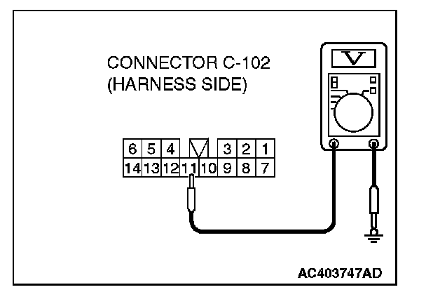
2. Measure the voltage between terminal number 11 and ground by backprobing.
The measured value should be approximately 12 volts (battery positive voltage).
Q: Does the measured voltage correspond with this range?
YES: Either repair or replace the radio and CD player. Check that a memory is retained.
NO: Go to Step 2.
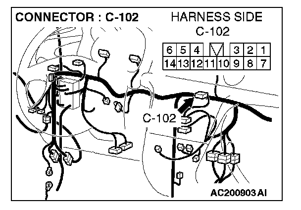
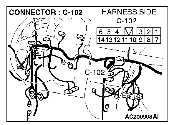
STEP 2. Check radio and CD player connector C-102 for damage.
Q: Is radio and CD player connector C-102 in good condition?
YES: Go to Step 5.
NO: Repair or replace the connector. Check that a memory is retained.
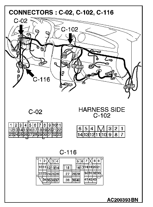
STEP 5. Check the wiring harness between radio and CD player connector C-102 (terminal 11) and battery.
NOTE: Also check joint connector C-02 and intermediate connector C-116. If joint connector C-02 or intermediate connectors C-116 is damaged, repair or replace the connector as described in Harness Connector Inspection.
Q: Are the wiring harness between radio and CD player connector C-22 (terminal 11) and battery in good condition?
YES: Repair or replace the radio and CD player. Check that a memory is retained.
NO: Repair the wiring harness. Check that a memory is retained.