P1021
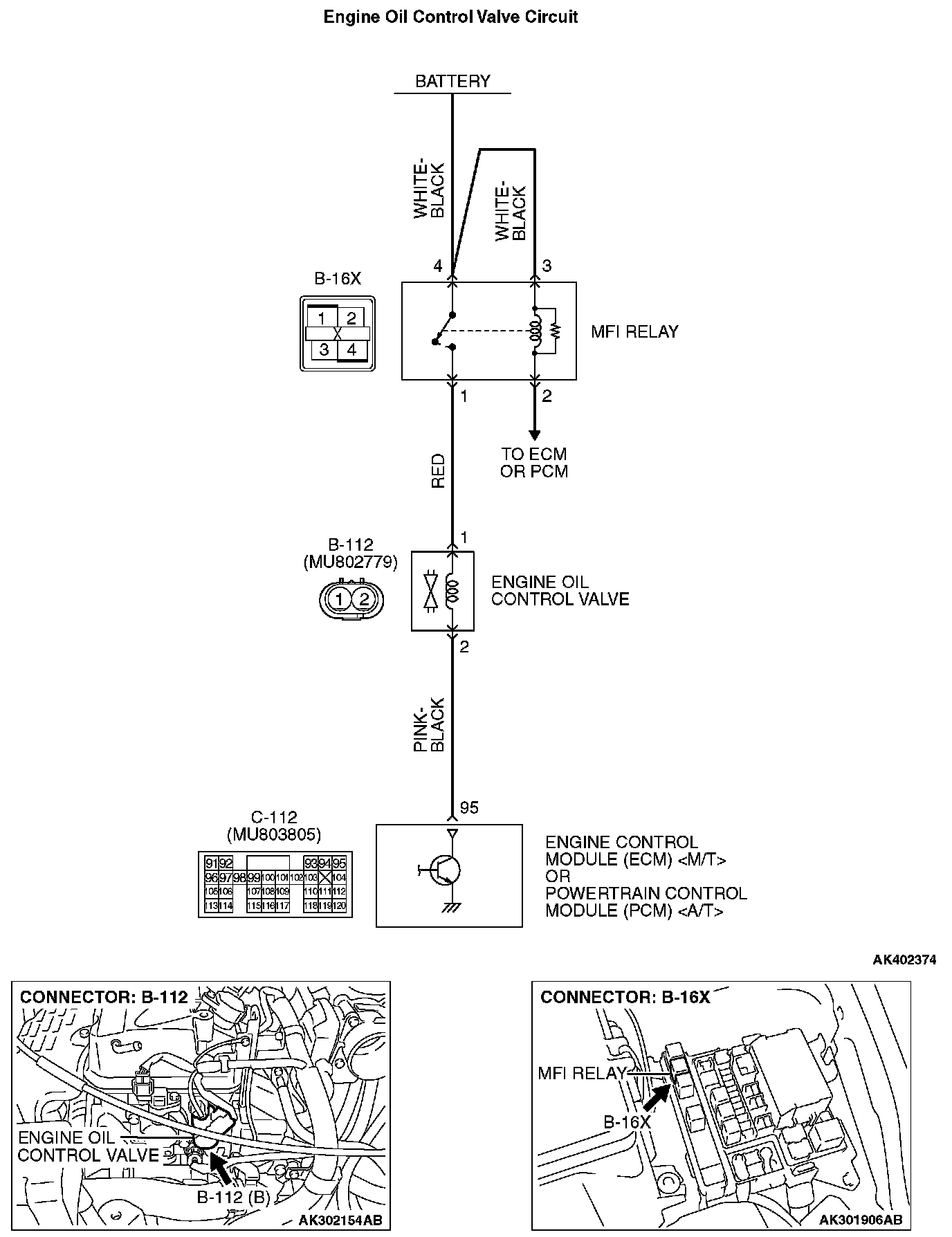
DTC P1021: Engine Oil Control Valve CircuitEngine Oil Control Valve Circuit Part 1:
Engine Oil Control Valve Circuit Part 2:
CIRCUIT OPERATION
- The engine oil control valve power is supplied from the MFI relay (terminal No. 1).
- The ECM
TECHNICAL DESCRIPTION
- The engine oil control valve switches the cams to operate the MIVEC system in the low-speed or high-speed mode in accordance with the signals from the ECM
DTC SET CONDITIONS
Logic Flow Chart:
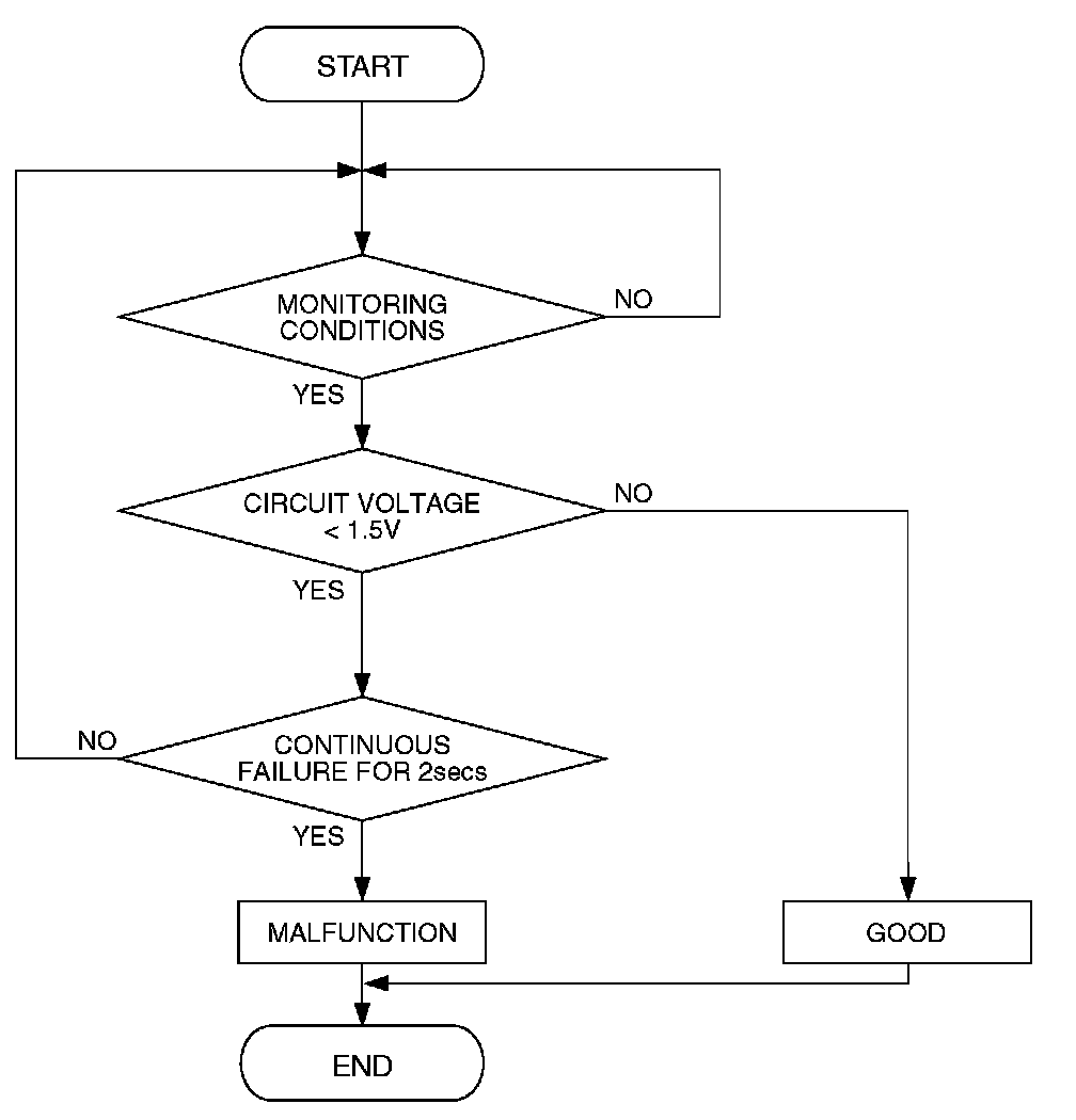
Logic Flow Chart
Check Conditions
- Ignition switch: "ON"
- Engine oil control valve is "OFF"
- Battery positive voltage is between 10 and 16.5 volts.
- 0.1 second has elapsed after the above mentions have been met.
Judgement Criterion
- The ECM
OBD-II DRIVE CYCLE PATTERN
Refer to Diagnostic Function - OBD-II Drive Cycle - Pattern 22. OBD-II Drive Cycle Pattern Lists
TROUBLESHOOTING HINTS (The most likely causes for this code to be set are:)
- Engine oil control valve failed.
- Open or shorted engine oil control valve circuit, or harness damage or connector damage.
- ECM failed.
- PCM failed.
DIAGNOSIS
Required Special Tools:
- MB991958: Scan Tool (MUT-III Sub Assembly)
- MB991824: V.C.I.
- MB991827: USB Cable
- MB991910: Main Harness A
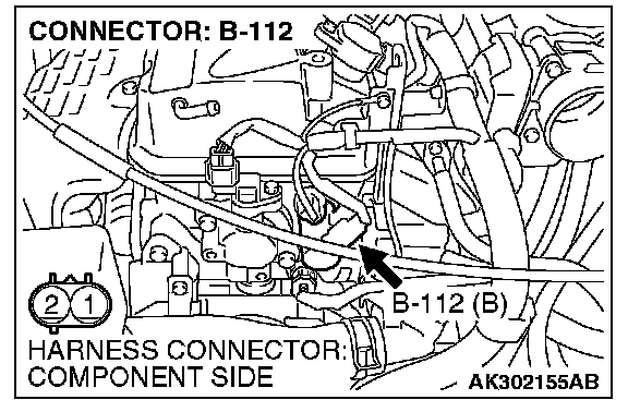
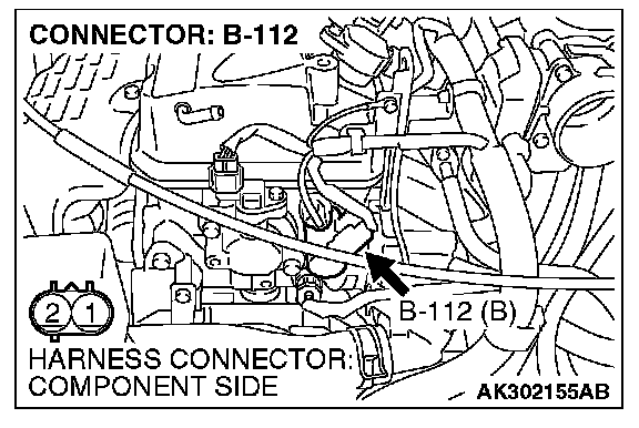
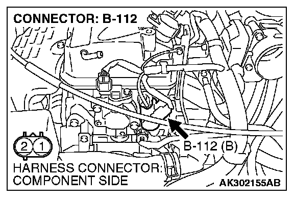
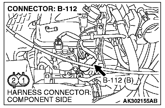
STEP 1. Check harness connector B-112 at the engine oil control valve for damage.
Q: Is the harness connector in good condition?
YES: Go to Step 2.
NO: Repair or replace it. Then go to Step 12.
STEP 2. Check the engine oil control valve.
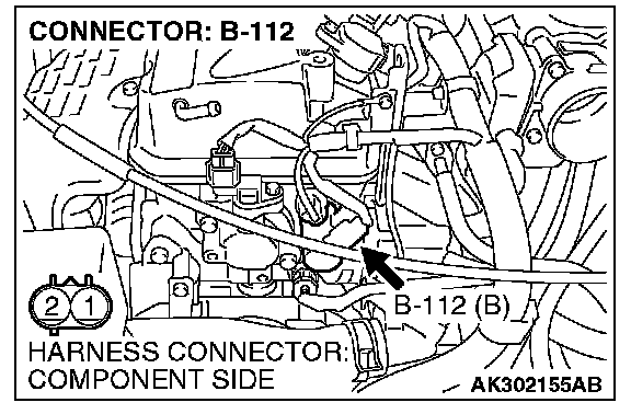
1. Disconnect the engine oil control valve connector B-112.
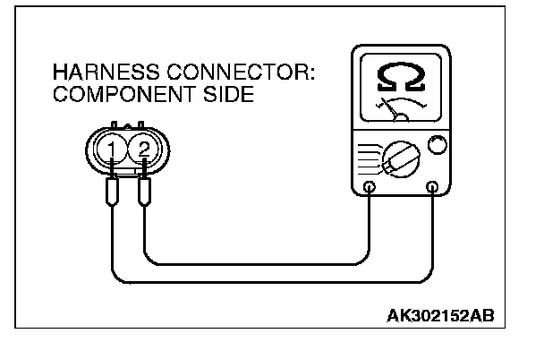
2. Measure the resistance between engine oil control valve side connector terminal No. 1 and No. 2.
Standard value: 6.9 -7.9 Ohms [at 20 degrees C (68 degrees F)]
Q: Is the measured resistance between 6.9 and 7.9 Ohms [at 20 degrees C (68 degrees F)]?
YES: Go to Step 3.
NO: Replace the engine oil control valve. Then go to Step 12.
STEP 3. Measure the power supply voltage at engine oil control valve harness side connector B-112.

1. Disconnect the connector B-112 and measure at the harness side.
2. Turn the ignition switch to the "ON" position.
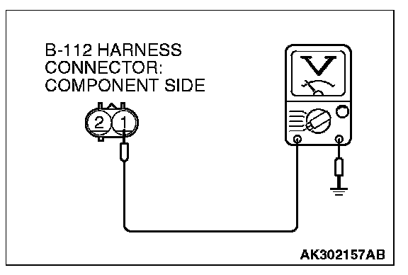
3. Measure the voltage between terminal No. 1 and ground.
- Voltage should be battery positive voltage.
4. Turn the ignition switch to the "LOCK" (OFF) position.
Q: Is battery positive voltage (approximately 12 volts) present?
YES: Go to Step 5.
NO: Go to Step 4.
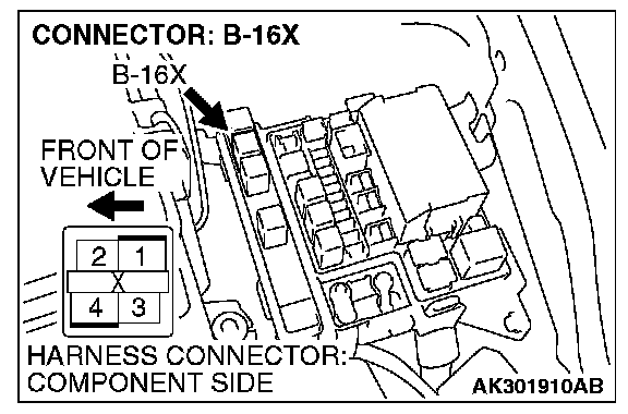
STEP 4. Check harness connector B-16X at MFI relay for damage.
Q: Is the harness connector in good condition?
YES: Repair harness wire between MFI relay connector B-16X (terminal No. 1) and engine oil control valve connector B-112 (terminal No. 1) because of open circuit or short circuit to ground. Then go to Step 12.
NO: Repair or replace it. Then go to Step 12.
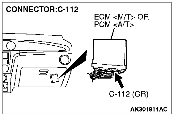
STEP 5. Measure the power supply voltage at ECM
1. Do not disconnect the connector C-112.
2. Turn the ignition switch to the "ON" position.
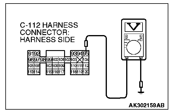
3. Measure the voltage between terminal No. 95 and ground by backprobing.
- Voltage should be battery positive voltage.
4. Turn the ignition switch to the "LOCK" (OFF) position.
Q: Is battery positive voltage (approximately 12 volts) present?
YES: Go to Step 8.
NO: Go to Step 6.
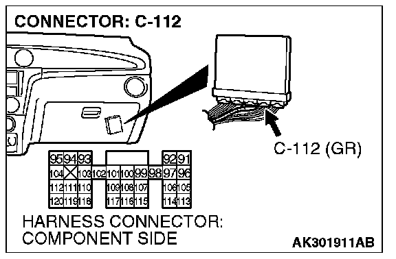
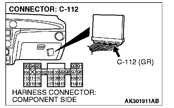
STEP 6. Check harness connector C-112 at ECM
Q: Is the harness connector in good condition?
YES: Go to Step 7.
NO: Repair or replace it. Then go to Step 12.

STEP 7. Check for open circuit and short circuit to ground between engine oil control valve connector B-112 (terminal No. 2) and ECM
Q: Is the harness wire in good condition?
YES: Replace the ECM or the PCM. Then go to Step 12.
NO: Repair it. Then go to Step 12.
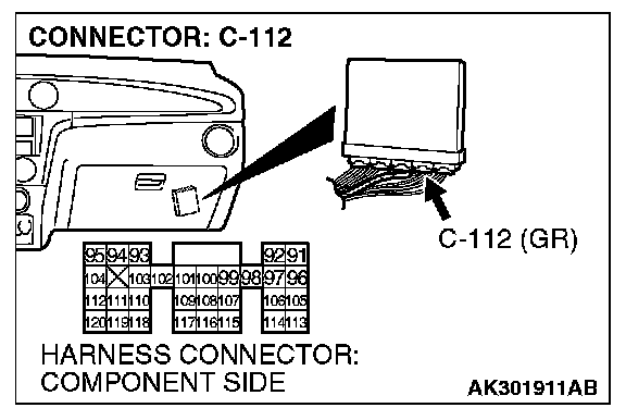
STEP 8. Check harness connector C-112 at ECM
Q: Is the harness connector in good condition?
YES: Go to Step 9.
NO: Repair or replace it. Then go to Step 12.
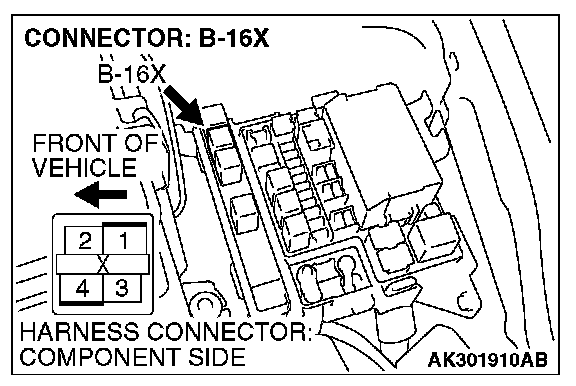
STEP 9. Check for harness damage between MFI relay connector B-16X (terminal No. 1) and engine oil control valve connector B-112 (terminal No. 1).
Q: Is the harness wire in good condition?
YES: Go to Step 10.
NO: Repair it. Then go to Step 12.

STEP 10. Check for harness damage between engine oil control valve connector B-112 (terminal No. 2) and ECM
Q: Is the harness wire in good condition?
YES: Go to Step 11.
NO: Repair it. Then go to Step 12.
STEP 11. Check the trouble symptoms.
1. Carry out test drive with the drive cycle pattern. Refer to Diagnostic Function - OBD-II Drive Cycle - Pattern 22. OBD-II Drive Cycle Pattern Lists
2. Check the diagnostic trouble code (DTC).
Q: Is DTC P1021 set?
YES: Replace the ECM or the PCM. Then go to Step 12.
NO: It can be assumed that this malfunction is intermittent.
STEP 12. Test the OBD-II drive cycle.
1. Carry out a test drive with the drive cycle pattern. Refer to Diagnostic Function - OBD-II Drive Cycle - Pattern 22. OBD-II Drive Cycle Pattern Lists
2. Check the diagnostic trouble code (DTC).
Q: Is DTC P1021 set?
YES: Retry the troubleshooting.
NO: The inspection is complete.