Part 2
DTC 27 (P0705): Transmission Range Switch System (Open Circuit)(continued)DIAGNOSIS
Required Special Tool:
^ MB991958: Scan Tool (MUT-III sub assembly)
^ MB991824: V.C.I.
^ MB991827: MUT-III USB Cable
^ MB991910: MUT-III Main Harness A
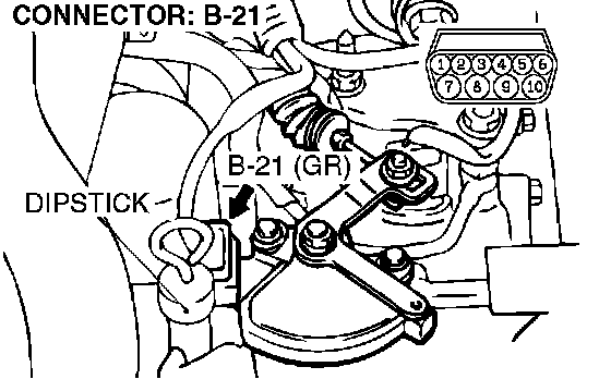
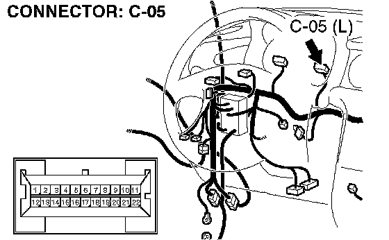
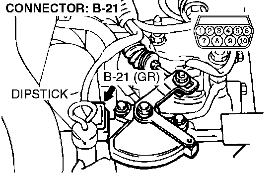
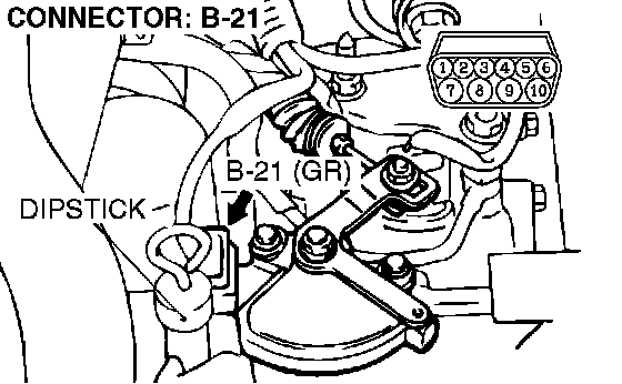
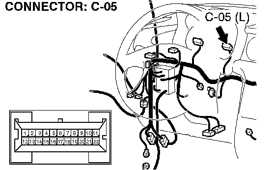
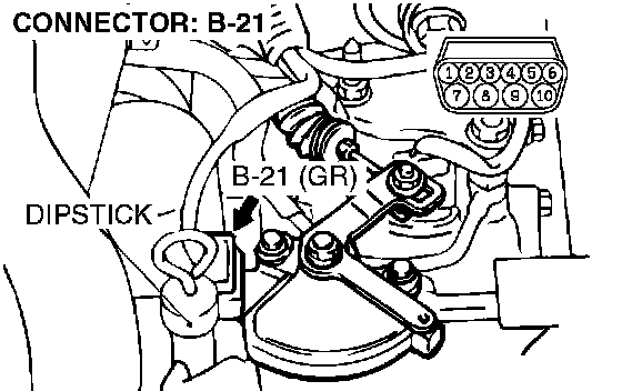
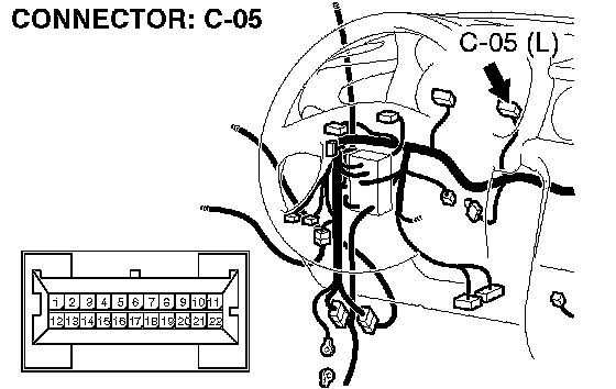
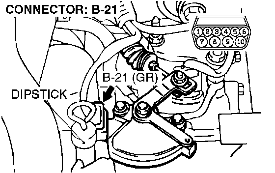
STEP 20. Check the harness for short circuit to ground between transmission range switch connector B-21 terminal 7 and combination meter connector C-05 terminal 3.
Q: Is the harness wire in good condition?
YES: Go to Step 5.
NO: Repair or replace the harness wire.
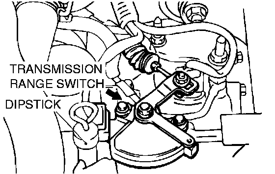
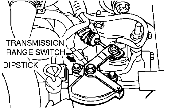
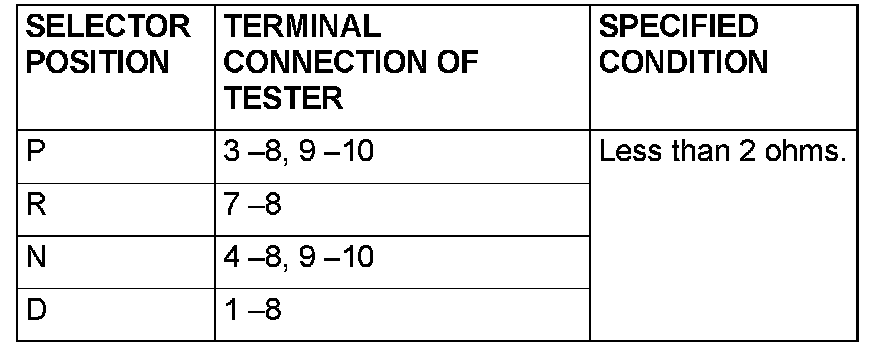
STEP 21. Check the transmission range switch.
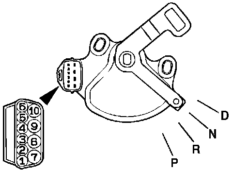
Measure the resistance between the terminals for each selector position as indicated in the table.
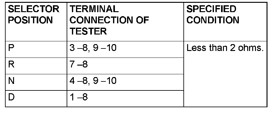
Q: Does the resistance measure less than 2 ohms for each selector position?
YES: Go to Step 22.
NO: Replace the transmission range switch.
STEP 22. Check transmission range switch connector B-21 for loose, corroded or damaged terminals, or terminals pushed back in the connector.
Q: Are the connector and terminals in good condition?
YES: Go to Step 23.
NO: Repair or replace the damaged components.
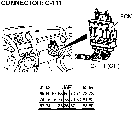
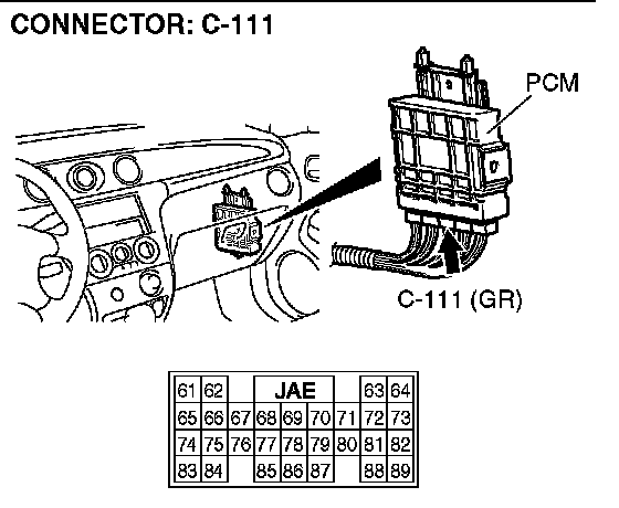
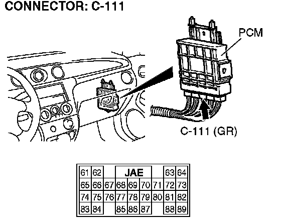
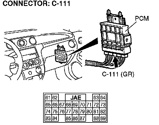
STEP 23. Measure the transmission range switch output voltage at PCM connector C-111 by backprobing.
1) Do not disconnect connector C-111.
2) Turn the ignition switch to the ON position.
3) Move the selector lever to the N position.
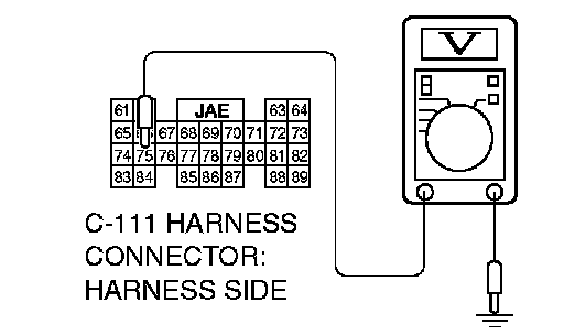
4) Measure the voltage between terminal 75 and ground by backprobing.
^ The voltage should measure battery positive voltage.
5) Turn the ignition switch to the LOCK (OFF) position.
Q: Does the voltage measure battery positive voltage?
YES: Go to Step 13.
NO: Go to Step 24.
STEP 24. Check PCM connector C-111 for loose, corroded or damaged terminals, or terminals pushed back in the connector.
Q: Are the connector and terminals in good condition?
YES: Go to Step 25.
NO: Repair or replace the damaged components.
STEP 25. Check harness for open circuit or short circuit to ground between transmission range switch connector B-21 terminal 4 and PCM connector C-111 terminal 75.
Q: Is the harness wire in good condition?
YES: Go to Step 26.
NO: Repair or replace the harness wire.
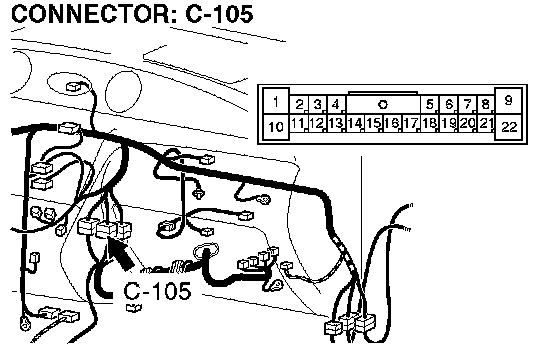
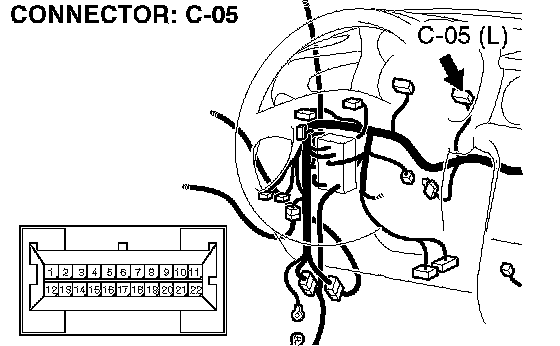
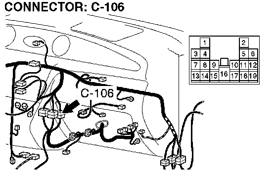
STEP 26. Check intermediate connector C-105 and combination meter connector C-05 for loose, corroded or damaged terminals, or terminals pushed back in the connector.
Q: Are the connectors and terminals in good condition?
YES: Go to Step 27.
NO: Repair or replace the damaged components.
STEP 27. Check the harness for short circuit to ground between transmission range switch connector B-21 terminal 4 and combination meter connector C-05 terminal 2.
Q: Is the harness wire in good condition?
YES: Go to Step 5.
NO: Repair or replace the harness wire.
STEP 28. Check the transmission range switch.
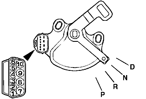
Measure the resistance between the terminals for each selector position as indicated in the table.
Q: Does the resistance measure less than 2 ohms for each selector position?
YES: Go to Step 29.
NO: Replace the transmission range switch.
STEP 29. Check transmission range switch connector B-21 for loose, corroded or damaged terminals, or terminals pushed back in the connector.

Q: Are the connector and terminals in good condition?
YES: Go to Step 30.
NO: Repair or replace the damaged components.
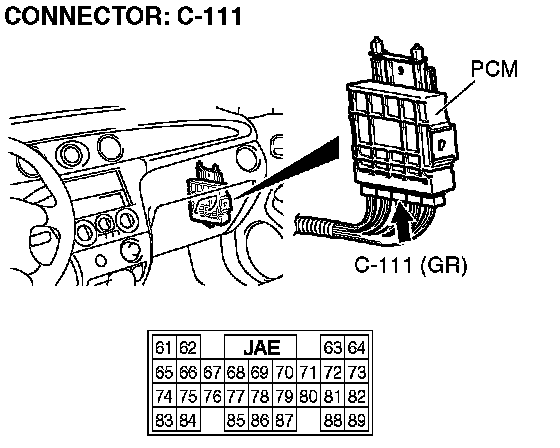
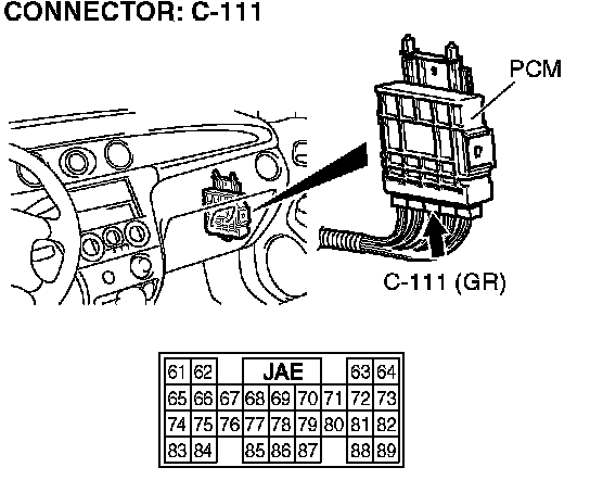
STEP 30. Measure the transmission range switch output voltage at PCM connector C-111 by backprobing.
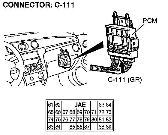
1) Do not disconnect connector C-111.
2) Turn the ignition switch to the ON position.
3) Move the selector lever to the D position.
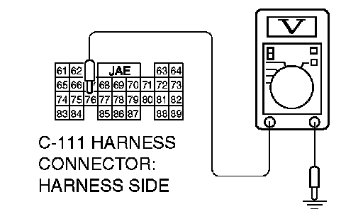
4) Measure the voltage between terminal 76 and ground by backprobing.
^ The voltage should measure battery positive voltage.
5) Turn the ignition switch to the LOCK (OFF) position.
Q: Does the voltage measure battery positive voltage?
YES: Go to Step 13.
NO: Go to Step 31.
STEP 31. Check PCM connector C-111 for loose, corroded or damaged terminals, or terminals pushed back in the connector.
Q: Are the connector and terminals in good condition?
YES: Go to Step 32.
NO: Repair or replace the damaged components.
STEP 32. Check harness for open circuit or short circuit to ground between transmission range switch connector B-21 terminal 1 and PCM connector C-111 terminal 76.

Q: Is the harness wire in good condition?
YES: Go to Step 33.
NO: Repair or replace the harness wire.
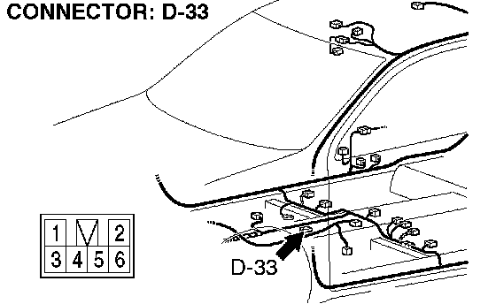
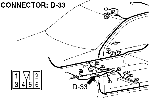
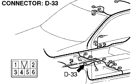
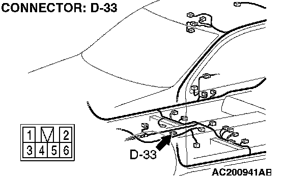
STEP 33. Check shift switch assembly connector D-33, intermediate connector C-106 and combination meter connector C-05 for loose, corroded or damaged terminals, or terminals pushed back in the connector.

Q: Are the connectors and terminals in good condition?
YES: Go to Step 34.
NO: Repair or replace the damaged components.
STEP 34. Check harness for short circuit to ground between transmission range switch connector B-21 terminal 1 and shift switch assembly connector D-33 terminal 1.
Q: Is the harness wire in good condition?
YES: Go to Step 35.
NO: Repair or replace the harness wire.
STEP 35. Check the harness for short circuit to ground between shift switch assembly connector D-33 terminal 2 and combination meter connector C-05 terminal 1.

Q: Is the harness wire in good condition?
YES: Go to Step 5.
NO: Repair or replace the harness wire.
STEP 36. Check PCM connector C-111 and shift switch assembly connector D-33 for loose, corroded or damaged terminals, or terminals pushed back in the connector.

Q: Are the connector and terminals in good condition?
YES: Go to Step 37.
NO: Repair or replace the damaged components.
STEP 37. Check harness for short circuit to ground between shift switch assembly connector D-33 terminal 4 and PCM connector C-111 terminal 85.
Q: Is the harness wire in good condition?
YES: Go to Step 5.
NO: Repair or replace the harness wire.