DTC 42
DTC 42: Mode Selection Damper Control Motor and Potentiometer activating systemMode Selection Damper Control Motor And Potentiometer Circuit Part 1:
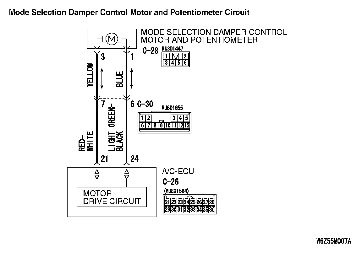
Mode Selection Damper Control Motor And Potentiometer Circuit Part 2:
DTC SET CONDITION
- If the air mixing damper control motor does not work normally, DTC 42 will be set.
TROUBLESHOOTING HINT
- Malfunction of connector.
- Malfunction of the harness.
- Malfunction of the mode selection damper control motor and potentiometer.
- Malfunction of the A/C-ECU.
DIAGNOSIS
Required Special Tools:
- MB991223: Harness Set
- MB992006: Extra Fine Probe
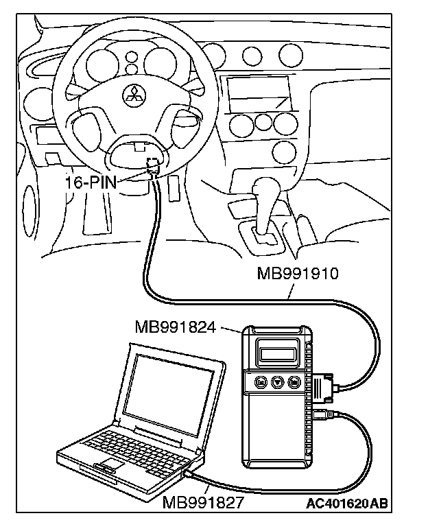
- MB991958: Scan Tool (MUT-III Sub Assembly)
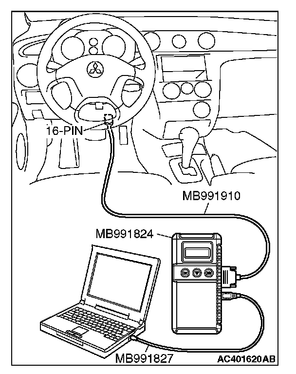
- MB991824: Vehicle Communication Interface (V.C.I.)
- MB991827: MUT-III USB Cable
- MB991910: MUT-III Main Harness A (Vehicles with CAN communication system)
STEP 1. Using scan tool MB991958, check actuator test.
CAUTION: To prevent damage to scan tool MB991958, always turn the ignition switch to the "LOCK" (OFF) position before connecting or disconnecting scan tool MB991958.
1. Connect scan tool MB991958 to the data link connector.
2. Start the engine.
3. Use scan tool MB991958 to run the actuator test.
Item 08: air mix damper motor (FACE position) Item 09: air mix damper motor (FOOT position) Item 10: air mix damper motor (DEF position)
- Check that the mode selection damper control motor operates.
4. Turn the ignition switch to the "LOCK" (OFF) position.
Q: Is the sensor within the specified range?
YES: Replace the A/C-ECU. Then go to Step 5.
NO: Go to Step 2.
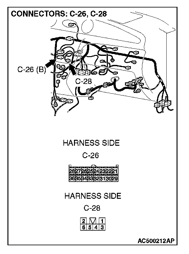
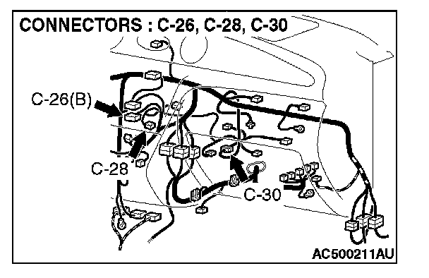
STEP 2. Check A/C-ECU connector C-26 and mode selection damper control motor and potentiometer connector C-28 for loose, corroded or damaged terminals, or terminals pushed back in the connector.
Q: Are A/C-ECU connector C-26 and mode selection damper control motor and potentiometer connector C-28 in good condition?
YES: Go to Step 3.
NO: Repair or replace the connector. Then go to Step 5.
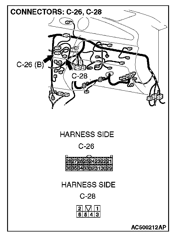
STEP 3. Check the wiring harness between A/C-ECU connector C-26 (terminals 21 and 24) and mode selection damper control motor and potentiometer connector C-28 (terminals 3 and 1).
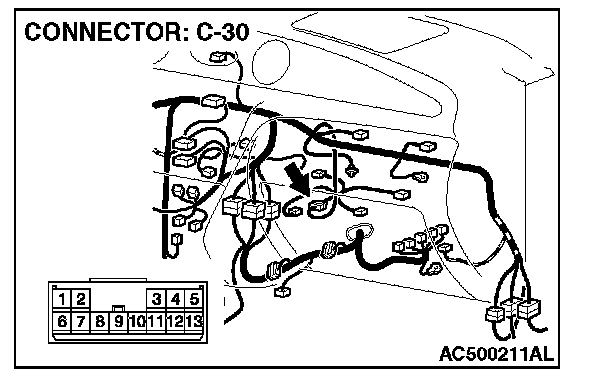
NOTE: Also check intermediate connector C-30 for loose, corroded, or damaged terminals, or terminals pushed back in the connector. If intermediate connector C-30 is damaged, repair or replace the connector as described in Harness Connector Inspection.
Q: Are the wiring harnesses between A/C-ECU connector C-26 (terminals 21 and 24) and mode selection damper control motor and potentiometer connector C-28 (terminals 3 and 1) in good condition?
YES: Go to Step 4.
NO: Repair the wiring harness. Then go to Step 5.
STEP 4. Check the mode selection damper control motor.
CAUTION: Do not apply battery voltage when the damper is in the FACE or DEF position.
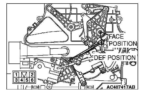
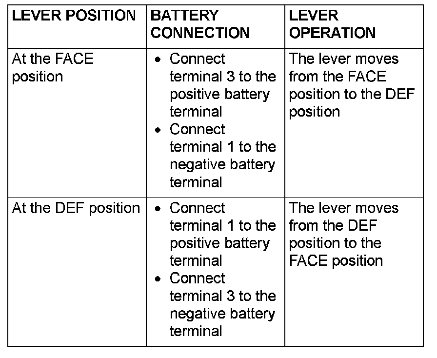
Check the mode selection damper control motor by the procedures.
Q: Is the mode selection damper control motor in good condition?
YES: Go to Step 5.
NO: Replace the mode selection damper control motor and potentiometer. Then go to Step 5.
STEP 5. Recheck for diagnostic trouble code.
Check again if the DTC is set.
1. Connect scan tool MB991958 to the data link connector
2. Turn the ignition switch to the "ON" position.
3. Check if the DTC is set.
4. Turn the ignition switch to the "LOCK" (OFF) position.
Q: Is the check result satisfactory?
YES: The procedure is complete.
NO: Return to Step 1.