DTC 31
DTC 31: Air Mixing Damper Control Motor and Potentiometer systemAir Mixing Damper Control Motor Potentiometer Circuit Part 1:
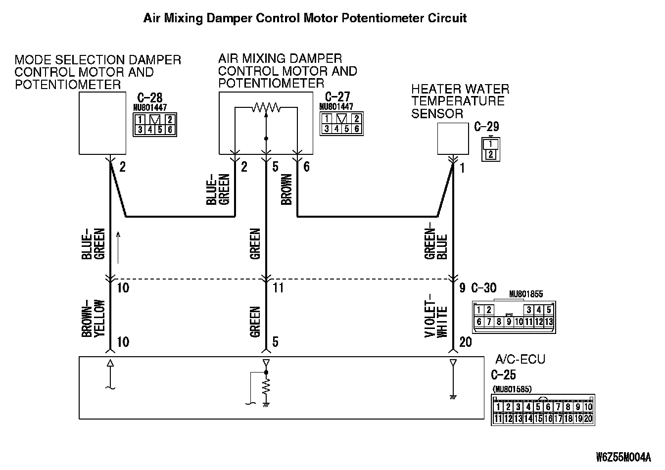
Air Mixing Damper Control Motor Potentiometer Circuit Part 2:
DTC SET CONDITION
- DTC 31 is set if there is an open or short circuit in the potentiometer input circuit, or if there is an open circuit in the power circuit or earth circuit.
TROUBLESHOOTING HINT
- Malfunction of connector.
- Malfunction of the harness.
- Malfunction of the air mixing damper control motor and potentiometer.
- Malfunction of the A/C-ECU.
DIAGNOSIS
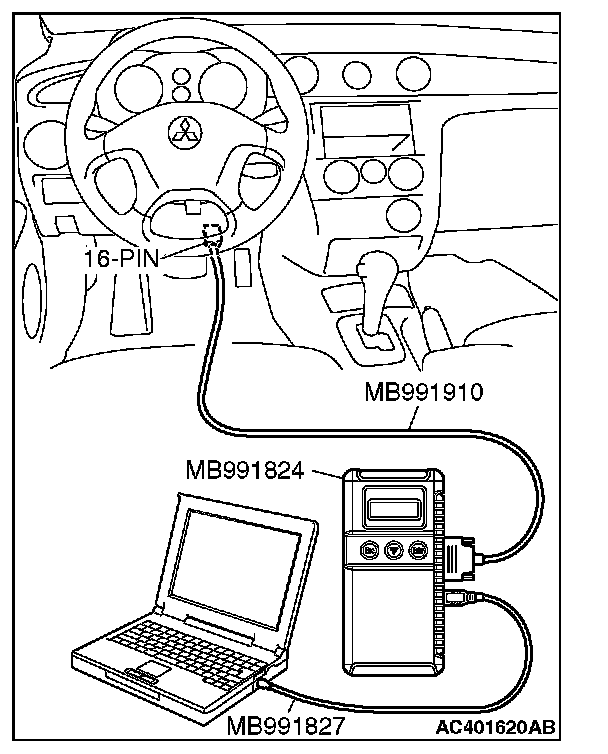
Required Special Tools:
- MB991223: Harness Set
- MB992006: Extra Fine Probe
- MB991958: Scan Tool (MUT-III Sub Assembly)
- MB991824: Vehicle Communication Interface (V.C.I.)
- MB991827: MUT-III USB Cable
- MB991910: MUT-III Main Harness A (Vehicles with CAN communication system)
STEP 1. Using scan tool MB991958, check data list.
CAUTION: To prevent damage to scan tool MB991958, always turn the ignition switch to the "LOCK" (OFF) position before connecting or disconnecting scan tool MB991958.
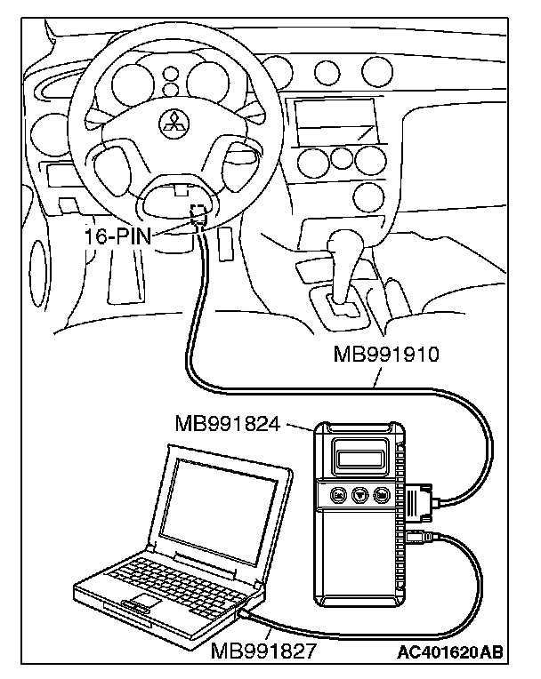
1. Connect scan tool MB991958 to the data link connector.
2. Start the engine.
3. Set scan tool MB991958 to the data reading mode.
Item 31: air mix potentiometer.
- Check that the set position of the heater control matches the displayed position on the scan tool.
4. Turn the ignition switch to the "LOCK" (OFF) position.
Q: Is the sensor within the specified range?
YES: Replace the A/C-ECU. Then go to Step 5.
NO: Go to Step 2.
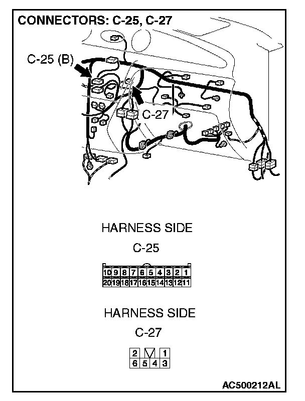
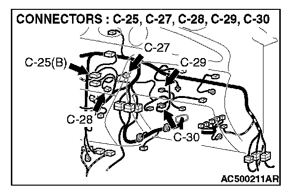
STEP 2. Check A/C-ECU connector C-25 and air mixing damper control motor and potentiometer connector C-27 for loose, corroded or damaged terminals, or terminals pushed back in the connector.
Q: Are A/C-ECU connector C-25 and air mixing damper control motor and potentiometer connector C-27 in good condition?
YES: Go to Step 3.
NO: Repair or replace the connector. Then go to Step 5.
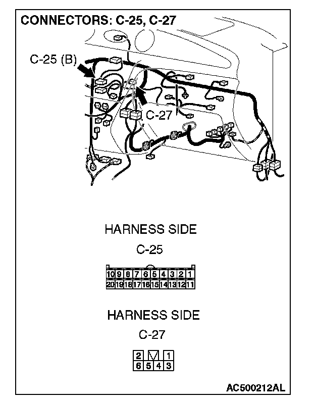
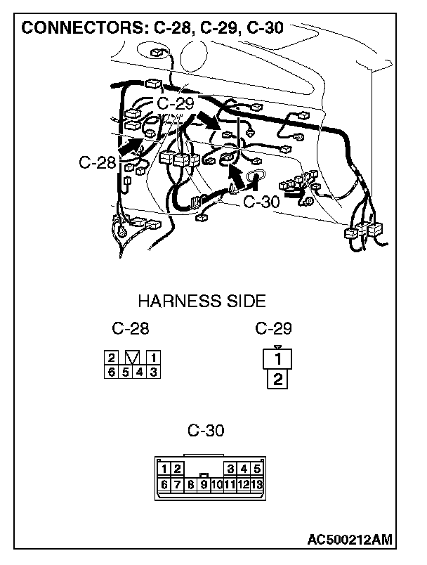
STEP 3. Check the wiring harness between A/C-ECU connectors C-25 (terminals 10, 5 and 20) and air mixing damper control motor and potentiometer connector C-27 (terminals 2, 5 and 6).
NOTE: Also check intermediate connector C-30, mode selection damper control motor and potentiometer connector C-28 and heater water temperature sensor connector C-29 for loose, corroded, or damaged terminals, or terminals pushed back in the connector. If intermediate connector C-30, mode selection damper control motor and potentiometer connector C-28 and heater water temperature sensor connector C-29 is damaged, repair or replace the connector as described in Harness Connector Inspection.
Q: Are the wiring harness between A/C-ECU connector C-25 (terminals 10, 5 and 20) and air mixing damper control motor and potentiometer connector C-27 (terminals 2, 5 and 6) in good condition?
YES: Go to Step 4.
NO: Repair the wiring harness. Then go to Step 5.
STEP 4. Check the air mixing damper control motor and
potentiometer.
AIR MIXING DAMPER CONTROL MOTOR CHECK
CAUTION: Do not apply battery voltage when the damper is in the MAX COOL or MAX HOT position.
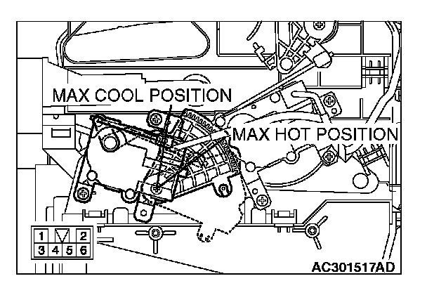
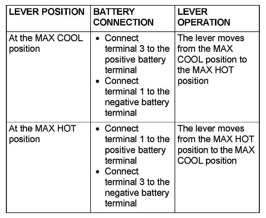
Operate the air mixing damper control motor as described in the table.
POTENTIOMETER CHECK
Measure the resistances between connector terminals 2 and 5, and between 5 and 6, while the air mixing damper control motor is running. The resistances should change gradually within the standard value.
Standard value: 0.65 (MAX HOT)- 5.35 (MAX COOL) kOhms
Q: Are the air mixing damper control motor and potentiometer in good condition?
YES: Replace the A/C-ECU. Then go to Step 5.
NO: Replace the air mixing damper control motor and potentiometer. Then go to Step 5.
STEP 5. Recheck for diagnostic trouble code.
Check again if the DTC is set.
1. Connect scan tool MB991958 to the data link connector
2. Turn the ignition switch to the "ON" position.
3. Check if the DTC is set.
4. Turn the ignition switch to the "LOCK" (OFF) position.
Q: Is the check result satisfactory?
YES: The procedure is complete.
NO: Return to Step 1.