DTC 13
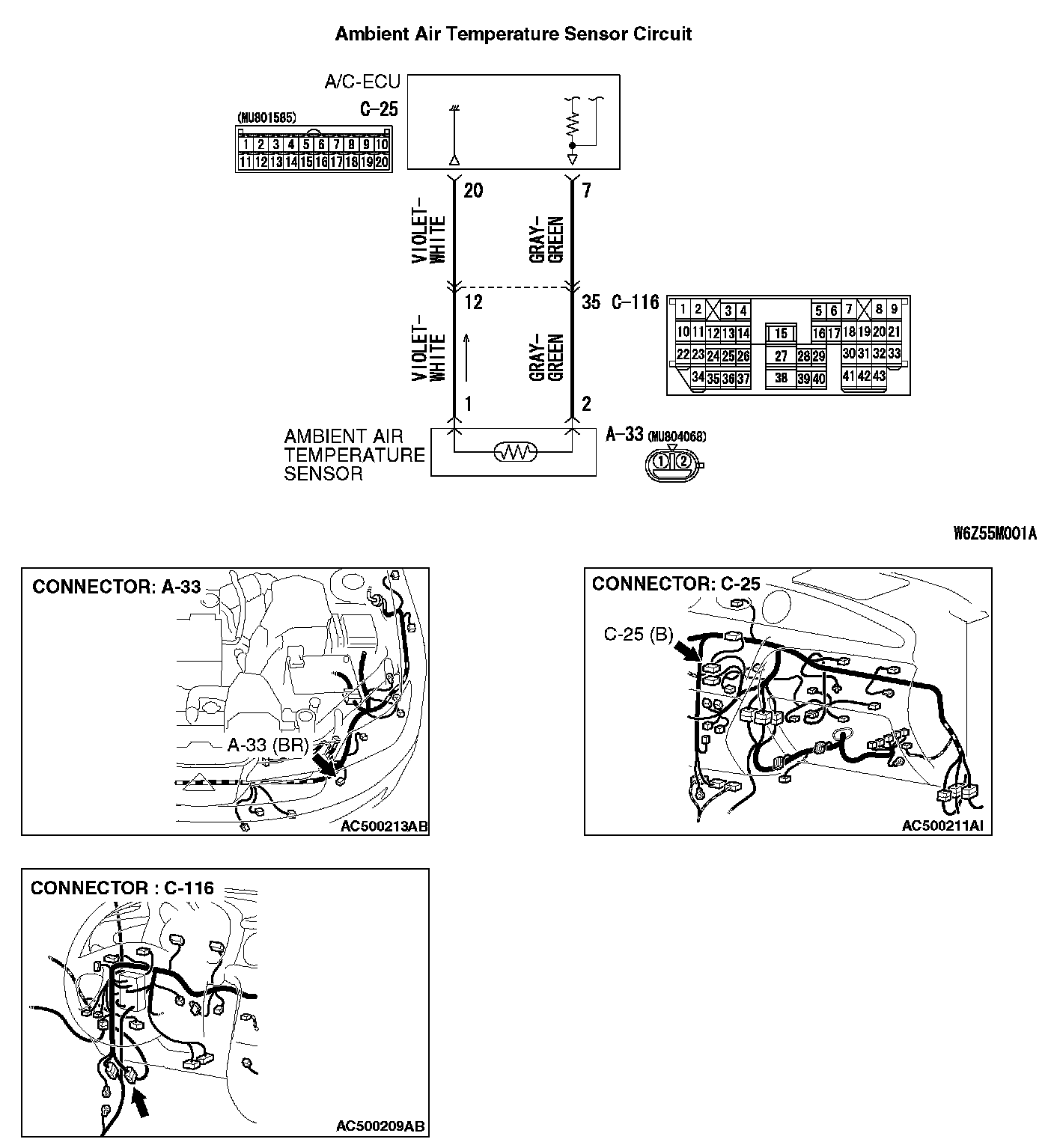
DTC 13: Ambient Air Temperature Sensor systemAmbient Air Temperature Sensor Circuit:
DTC SET CONDITION
- DTC 13 is set if there is a defective connector connection, or if there is an open circuit in the harness.
- DTC 14 is set if there is a short circuit in the ambient air temperature sensor input circuit.
TROUBLESHOOTING HINT
- Malfunction of connector.
- Malfunction of the harness.
- Malfunction of the ambient air temperature sensor.
- Malfunction of the A/C-ECU.
DIAGNOSIS
Required Special Tools:
- MB991223: Harness Set
- MB992006: Extra Fine Probe
- MB991958: Scan Tool (MUT-III Sub AassembAssembly8GMB991824: Vehicle Communication Interface (V.C.I.)
- MB991827: MUT-III USB Cable
- MB991910: MUT-III Main Harness A (Vehicles with CAN communication system)
STEP 1. Using scan tool MB991958, check data list.
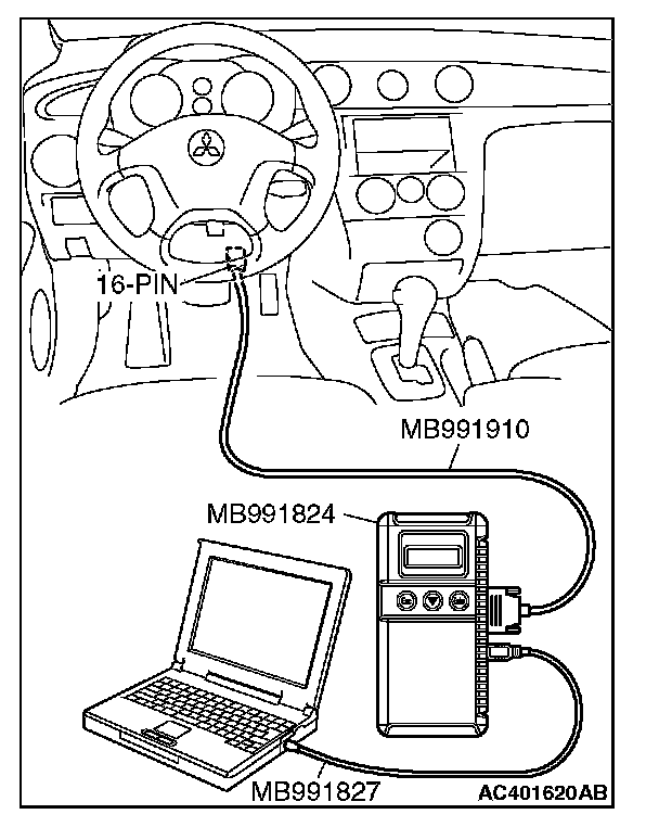
CAUTION: To prevent damage to scan tool MB991958, always turn the ignition switch to the "LOCK" (OFF) position before connecting or disconnecting scan tool MB991958.
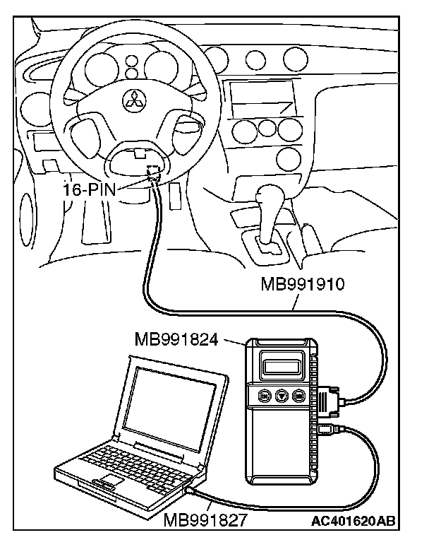
1. Connect scan tool MB991958 to the data link connector.
2. Start the engine.
3. Set scan tool MB991958 to the data reading mode. Item 13: Ambient air temperature sensor.
- Check that the ambient temperature matches the displayed value on the scan tool.
NOTE: When this DTC is set and the system is fail-safe status, the value of service data displays 20 degrees C.
4. Turn the ignition switch to the "LOCK" (OFF) position.
Q: Is the sensor within the specified range?
YES: Replace the A/C-ECU. Then go to Step 6.
NO: Go to Step 2.
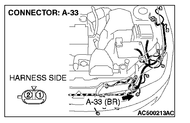
STEP 2. Check ambient air temperature sensor connector A-33 for loose, corroded or damaged terminals, or terminals pushed back in the connector.
Q: Is ambient air temperature sensor connector A-33 in good condition?
YES: Go to Step 3.
NO: Repair or replace the connector. Then go to Step 6.
STEP 3. Check the ambient air temperature sensor.
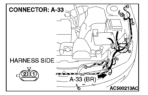
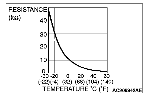
1. Disconnect ambient air temperature sensor connector A-33.
2. Measure the resistance between the sensor terminals under at least two temperatures. The resistance values should meet the values shown.
NOTE: The temperature should be within the shown range.
Q: Is the ambient air temperature sensor in good condition?
YES: Go to Step 4.
NO: Replace the ambient air temperature sensor. Then go to Step 6.
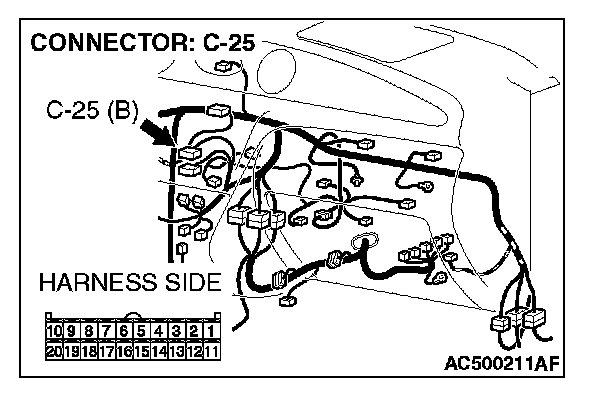
STEP 4. Check A/C-ECU connector C-25 for loose, corroded or damaged terminals, or terminals pushed back in the connector.
Q: Is A/C-ECU connector C-25 in good condition?
YES: Go to Step 5.
NO: Repair or replace the connector. Then go to Step 6.
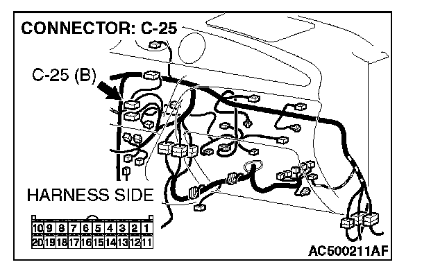
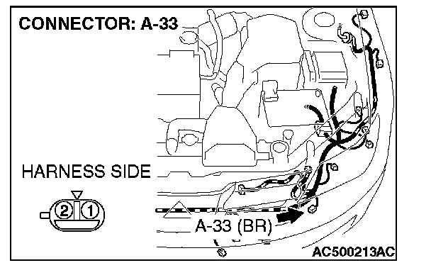
STEP 5. Check the wiring harness between A/C-ECU connector C-25 (terminals 7 and 20) and ambient air temperature sensor connector A-33 (terminals 2 and 1).
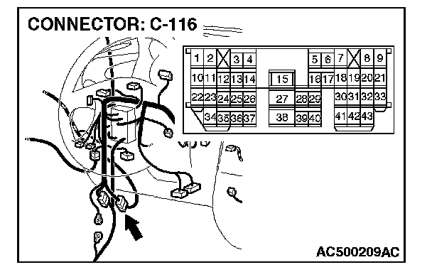
NOTE: Also check intermediate connector C-116 for loose, corroded, or damaged terminals, or terminals pushed back in the connector. If intermediate connector C-116 is damaged, repair or replace the connector as described in Harness Connector Inspection.
Q: Are the wiring harness between A/C-ECU connector C-25 (terminals 7 and 20) and ambient air temperature sensor connector A-33 (terminals 2 and 1) in good condition?
YES: Replace the A/C-ECU. Then go to Step 6.
NO: Repair the wiring harness. Then go to Step 6.
STEP 6. Recheck for diagnostic trouble code.
Check again if the DTC is set.
1. Connect scan tool MB991958 to the data link connector
2. Turn the ignition switch to the "ON" position.
3. Check if the DTC is set.
4. Turn the ignition switch to the "LOCK" (OFF) position.
Q: Is the check result satisfactory?
YES: The procedure is complete.
NO: Return to Step 1.